5.2 Squished Circles and Ellipses
5.2 " Squished " Circles and Ellipses
I've often been amazed “ and frequently aggravated “ by the number of incomplete or oddball circles required in drafting. Back in my board days, arcs were seldom a problem. I just used my circle template and drew as much as I needed. Ellipses, however, required the purchase of specific templates “ often several! There were, of course, templates that tried to provide almost every dimensional ellipse the draftsman might need “ from 25 ° to 80 °, and from ¼" to 6". But the ellipse I needed would inevitably fall into an oddball degree or size .
Ellipses are one of those things that AutoCAD makes quite a bit easier than plastic templates or clumsy compass attempts to create oddball shapes . Let's look at the command sequence (refer to Figure 5.2a).
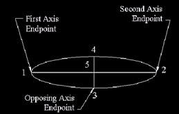
Figure 5.2a:
Command: ellipse (or el )
Specify axis endpoint of ellipse or [Arc/Center]: [select the first axis endpoint]
Specify other endpoint of axis: [select the opposite axis endpoint]
Specify distance to other axis or [Rotation]: [select the opposing axis endpoint]
The basic ellipse is really very easy to draw regardless of rotation or dimension. But as you can see, we've some options to consider.
-
Specify axis endpoint is the default. It allows you to draw the ellipse by selecting three axis endpoints, or two axis endpoints and a rotation angle.
-
The Arc option allows you to draw partial ellipses.
-
The Center option allows you to create an ellipse using a center point and two axis endpoints (rather than three axis endpoints).
Let's look at each of these options.
| Note | All of the options are also available in the Ellipse selection under the Draw pull-down menu or on the cursor menu once the Ellipse command has been entered. |
Do This: 5.2.1 Drawing Ellipses
-
Be sure you're still in the cir-ell drawing. If not, open it now. it's in the C:\Steps\Lesson05 folder.
-
Restore the Ellipse view.
-
Be sure the Running OSNAP is still set to endpoint.
-
Follow these steps.
Tools
Command Sequence
Steps

Ellipse Button
Command: el
1. Type the Ellipse command or el hotkey at the command prompt. Alternately, you can pick the Ellipse button on the Draw toolbar.
Specify axis endpoint of ellipse or [Arc/Center]:
2. Select the endpoint at point 1 of the top set of lines. (The lines aren't necessary; we use them here as guides only.)
Specify other endpoint of axis:
3. Select the endpoint at point 2.
Specify distance to other axis or [Rotation]:
4. Select the endpoint at either point 3 or point 4. Your ellipse looks like Figure 5.2.1.4a.
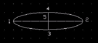
Figure 5.2.1.4a: Command: [enter]
5. Repeat the Ellipse command.
Specify axis endpoint of ellipse or [Arc/Center]: c
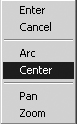
6. Type c (or select Center on the cursor menu) to access the Center option.

Specify center of ellipse: _int of
7. When AutoCAD prompts you for the center of the ellipse, select the OSNAP button for intersection, and then select point 5 of the second set of lines.
Specify endpoint of axis:
8. Select the endpoint at either point 1 or point 2.
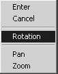
Specify distance to other axis or [Rotation]: r
9. Let's try the Rotation option. Type R or select Rotation on the cursor menu. ( Rotation refers to the angle at which the view sees the circle.)
Specify rotation around major axis: 75
10. Type in a rotation angle of 75 °. Your ellipse will look like the one in Step 4 (Figure 5.2.1.4a).

Command: [enter]
11. Repeat the Ellipse command or pick the Ellipse Arc button on the Draw toolbar. (If you use the Ellipse Arc button, skip Step 12 and go to Step 13.)
Specify axis endpoint of ellipse or [Arc/Center]: a
12. Type a (or select Arc on the cursor menu) to access the Arc option.
Specify axis endpoint of elliptical arc or [Center]:
13. Notice that you again have the option to select either an axis endpoint or the center of the ellipse. Let's use the default “ axis endpoint “ and select the endpoint at point 1 on the bottom set of lines.
Specify other endpoint of axis:
14. Select the endpoint at point 2.
Specify distance to other axis or [Rotation]:
15. Here again your options are repeated. You may select an axis endpoint of the opposing lines or enter R for a rotation angle. Select point 3.
Specify start angle or [Parameter]:
16. Now you have some new options. The Parameter option will yield the same result as the start angle option, but AutoCAD will use a different method of calculation. We'll use the default “ start angle . Type . ( refers to the first point you selected on the ellipse “ not the WCS's 0 °.)
Specify end angle or [Parameter/ Included angle]: 180
17. We started our arc at angle 0. An included angle is an angle measured counterclockwise from that point. We can type I followed by the angle we wish to use to create our arc. Or we can use the end angle approach and simply type the angle we want for the other end of the ellipse. Let's use the end angle default and type in 180 °.
Your ellipse looks like Figure 5.2.1.17a.
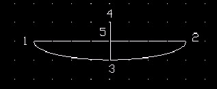
Figure 5.2.1.17a:
Command: qsave
18. Save the drawing, but don't exit.
Note By default, AutoCAD draws true ellipses. This enables you to find the center with an OSNAP.
The system variable PELLIPSE allows you to change the way AutoCAD draws ellipses. When set to the default , ellipses work the way we've seen. But set it to 1 and ellipses are drawn as polylines (just as rectangles are drawn). Both ellipses look the same, but the latter can be given width using the PEdit command. However, you can't easily find the center of the ellipse.
We'll learn about polylines and the PEdit command in Lesson 8.
You can now see that drawing ellipses isn't difficult “ although mastering the various approaches may take some time.
The ellipses we've drawn thus far have all existed in a true 2-dimensional plane. But you can also use ellipses to draw isometric circles . The procedure is simple but requires that you be in isometric mode . Otherwise, the Ellipse command won't provide the Isocircle option.
Let's look at this.
Do This: 5.2.2 Drawing Isometric Circles
-
Be sure you're still in the cir-ell drawing. If not, open it now. it's in the C:\Steps\Lesson05 folder.
-
Restore the Iso-Ellipse view.
-
Follow these steps.
Tools
Command Sequence
Steps
Command: sn
1. First, set your drawing to isometric mode. Your crosshairs will change (Figure 5.2.2.1a), as will the grid.
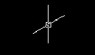
Figure 5.2.2.1a: Command: el
2. Repeat the Ellipse command.
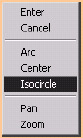
Specify axis endpoint of ellipse or [Arc/Center/Isocircle]: i
3. Type i (or select Isocircle on the cursor menu) to select the Isocircle option.

Specify center of isocircle: _nod of
4. Pick the Node button from the OSNAP toolbar, and then select the node in the center of the isometric rectangle.

5. See how the ellipse drags with the cursor in the current isometric plane? Toggle the plane using the F5 key to see how the ellipse changes. Stop toggling when the crosshairs return to the 90 °/30 ° position as shown in Figure 5.2.2.1a (Step 1).
Specify radius of isocircle or [Diameter]: 1
6. Notice that you may specify a radius or diameter. Let's use the default ( radius ) and type 1 . Your drawing looks like Figure 5.2.2.6a.
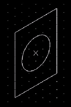
Figure 5.2.2.6a: Command: qsave
7. Save and close the drawing.
We've looked at circles and "squished" circles, partial ellipses (ellipse arcs), and isometric circles. Let's move on then to partial circles “ arcs.