16.1 Object Selection Settings
| Note | It'll be easier to understand Selection Settings and Grips if they're not both active at once. Let's begin our study of the Selection Settings by turning off Grips. Follow this procedure:
We'll reactivate them when we finish with this section of the text. |
There are several different selection settings designed to enhance your use of AutoCAD, each with a different system variable that you can set at the command line. But AutoCAD also provides a tab on the Options dialog box that might be easier to use than half-a- dozen system variables .
Figure 16.1a shows the dialog box with the Selections tab on top. ( Caution: Avoid changes to the other tabs at this time .) We'll concentrate on the Selection Modes frame for now. Let's start at the top.
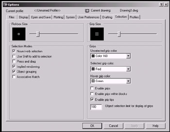
Figure 16.1a:
-
The "normal" approach to object modification in AutoCAD is to issue a command (like Erase ), and then select the object(s) of that that command. This approach can be called Verb/Noun as the command is invariably a verb and the object is a noun. Placing a check in the box next to Noun/Verb Selection (as the default does) means that AutoCAD will allow you to select the object of the command first, and then enter the command itself. The sequence (using the Erase command) looks like this:
Command: [select an object(s)]
Command: e
The system variable (sysvar) for Noun/Verb Selection is Pickfirst . Its default setting is 1 .
Do This: 16.1.1 Noun/Verb Selection
-
Open the Grips.dwg file the C:\Steps\Lesson16 folder. The drawing looks likeFigure 16.1.1a.

Figure 16.1.1a: -
Follow these steps.
Tools
Command Sequence
Steps

Command: v
1. Restore the Selection view. It looks like Figure 16.1.1.1a.

Figure 16.1.1.1a:No Button Available
Command: op
2. Enter the Options command by typing options or op . AutoCAD presents the Options dialog box. Pick the Selection tab to put it on top (Figure 16.1a).

3. Verify that there is a check in the Noun/Verb Selection check box.

4. Pick the OK button to return to the drawing.
Command:
5. Select the two lines that form the topmost point of the star (Figure 16.1.1.5a).

Figure 16.1.1.5a:
Command: e
6. Enter the Erase command. Notice that the lines are erased (Figure 16.1.1.6a).

Figure 16.1.1.6a:
Command: qsave
7. Save the drawing but don't exit.
-
In many Windows programs, selecting more than a single file or object requires you to hold down the Shift key. AutoCAD makes an allowance for users accustomed to this approach in the next option “ Use Shift to add to selection . If this box contains a check, selecting a second object will remove all previous objects from the selection set unless you hold down the Shift key while selecting.
The sysvar for Use Shift to add to selection is Pickadd . Its default setting is 1 .
Do This: 16.1.2 Using Shift to Add
-
Be sure you're still in the Grips.dwg file the C:\Steps\Lesson16 folder. If not, please open it now.
-
Follow these steps.
Tools
Command Sequence
Steps
No Button Available
Command: op
1. Enter the Options command by typing options or op . AutoCAD presents the Options dialog box. Be sure the Selection tab is on top.

2. Place a check in the Use Shift to add to selection check box.
3. Pick the OK button to return to the drawing.
Command: e
4. Enter the Erase command.
Select objects:
5. Select the horizontal line and then the two angled lines. Notice that as you select an object, the previously selected object is removed from the selection set (it's no longer highlighted.)
Select objects:
6. Now select the horizontal line. Then, while holding down the Shift key, select the angled lines. Notice that they all highlight.
Select objects: [enter]
7. Complete the command. The view now looks like Figure 16.1.2.7a.

Figure 16.1.2.7a: Command: qsave
8. Save the drawing but don't exit.
-
Again, in many Windows programs, placing a window around objects requires you to hold down the mouse button between corner selections. AutoCAD doesn't require this, but it allows for those who have become accustomed to it. A check in the Press and Drag box will change window creation to the following procedure:
-
Pick the first corner of the window.
-
Hold down the mouse button while positioning the crosshairs at the opposite corner.
-
Release the mouse button.
The sysvar for Press and Drag is Pickdrag . Its default setting is .
-
Do This: 16.1.3 Using Press and Drag
-
Be sure you're still in the Grips.dwg file the C:\Steps\Lesson16 folder. If not, please open it now.
-
Follow these steps.
Tools
Command Sequence
Steps
Command: op
1. Open the Options dialog box and place the Selections tab on top.

2. Remove the check from the Use Shift to add to selection check box, and add a check in the Press and drag check box.
3. Pick the OK button to return to the drawing.
Command: e
4. Enter the Erase command.
Select objects:
5. Try to begin an implied window as you normally would “ by selecting a point around the grid mark at coordinate 6,5 . Notice that you lose the window as soon as you release the mouse button.
Select objects:
6. Try it again. But this time hold down the mouse button as you move the lower right corner of the window to the grid mark around coordinate 11,0 . Now you get the window.
7. Release the mouse button to complete the selection window.
Select objects: [enter]
8. Hit enter to complete the command. The view is now empty.
9. Zoom to the limits of the drawing, which now looks like Figure 16.1.3.9a.

Figure 16.1.3.9a: Command: qsave
10. Save the drawing but don't exit.
-
We've been using Implied Windowing since Lesson 2. It enables us to pick an open area of the drawing to automatically begin a selection window. It's On by default. Removing the check will turn it off.
The sysvar for Implied Windowing is Pickauto . Its default setting is 1 .
-
A check in the Object Grouping option box means that AutoCAD will recognize grouped objects as a single object. We'll learn more about grouping in Lesson 18.
The sysvar for Object Grouping is Pickstyle . Its default setting is 1 . ( CTRL+A will also toggle object grouping On and Off.)
-
We'll look at the Associative Hatch option in Lesson 18 as well.
-
Below the Selection Modes frame, you'll find the Pickbox Size frame. Here you can adjust the size of the box used to select objects in a drawing. The slider bar makes adjustment easy as you can watch the sample selection box resize as it adjusts .
The sysvar for Pickbox Size is Pickbox . I prefer a setting of 4 or 5 (an allowance for my aging eyes “ many experienced users prefer 3 ), but adjust it until you're happy.