12.4 The Project
Now that you've had some practice in drawing and editing multilines , what do you think? Perhaps it's difficult to see the full benefits of these marvelous tools without some actual experience. Let's go back to our floor plan and add some walls!
Do This: 12.4.1 Add Some Walls
-
Open the MyFlr-Pln 12 file you created in the C:\Steps\Lesson12 folder. (If this file is unavailable, open flr_pln12 in the same folder.) The drawing looks like Figure 12.4.1a.
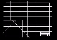
Figure 12.4.1a: -
Follow these steps. (Do not explode the multilines!)
Tools
Command Sequence
Steps
1. Set the Walls layer current.
Command: ml
2. Enter the MLine command.
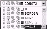
3. Draw a 5 ½" wide multiline to show the outer walls. Use the construction lines to guide you. (Hint: Set the multiline scale to 5.5 and use Top justification.)
Your drawing looks like Figure 12.4.1.3a.
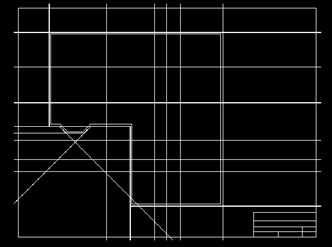
Figure 12.4.1.3a:Command: ml
4. Draw 4" wide multilines to show the inner walls. Use the construction lines to guide you. (Hint: Set the multiline scale to 4 and use Zero justification.)
Your drawing looks like Figure 12.4.1.4a.
Figure 12.4.1.4a:
Command: e
5. Erase the guidelines.
6. Cut the walls for doors and windows , as shown in Figure 12.4.1.6a.
-
All door openings are 36" except the smaller closet doors, which are 30".
-
Window openings are 42".
There are many possible ways to locate the openings. One suggestion follows (I will locate and size the left window on the back wall):
6a. Load the Points Lisp routine found in the C:\Steps\Lesson10 folder.
Command: pt
6b. Enter the command pt at the command line (this command has been defined by the Lisp routine you just loaded).
PICK A BASE POINT:
6c. AutoCAD asks you to pick a base point. Pick the left endpoint of the top wall.
HOW FAR? 12'7-3/8
6d. AutoCAD asks how far away to place the point. Enter the dimension given. (Be sure your Running OSNAPs are off.)
X, Y, OR P? x
6e. AutoCAD asks if the distance is along the X-plane, Y- plane, or in a Polar direction. Type X . AutoCAD places a node at that location.

Command: co
6f. We see by the number shown at this location that this is a 42" window. Copy the node 21" to the left and 21" to the right. The new nodes identify the edges of the window.
Command: mledit
6g. Using the multiline editing tools, break the wall using the nodes placed in Step 6f as guides. Then freeze the Markers layer.
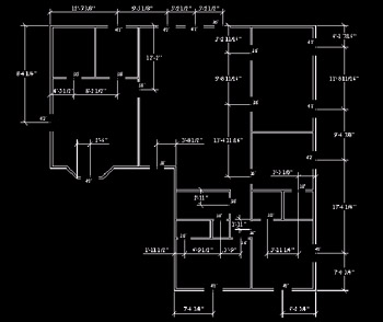
Figure 12.4.1.6a:Command: mledit
7. Open all tees (places where walls meet), as shown in Figure 12.4.1.6a.
Command: saveas
8. Save the drawing as MyFlrPln13 in the C:\Steps\Lesson13 folder, and exit.
-
Well, that was fun! Does your drawing look more like a floor plan now? Are you beginning to feel like a CAD operator?