| Objective: Manage TCP/IP routing. The last piece of the Windows Server 2003 routing puzzle is the routing port. A routing port is a device or a channel of a device that supports a single point-to-point connection. For an example of a device that acts as a port, think of a modem. Integrated Services Digital Network (ISDN) is an example of a channelized connection (also known as a multiport device). A Primary Rate Interface (PRI) ISDN connection can support two data channels, known as B-channels (short for bearer channels). Each of these B-channels can act as the port for a point-to-point connection. There is an additional 16KB D-channel (short for delta channel) that is used for session control and error handling. Step by Step 7.12 describes how to manage these ports. You need to have a modem configured on your test system to complete this exercise. Note: Why Can't I Add a Port in the Routing and Remote Access Console? In the Windows Server 2003 operating system, ports are physical devices. As such, they are added either through the Modems applet in the Control Panel or through the Add/Remove Hardware applet for devices that are added as internal port adapters (for example, an ISDN adapter). RRAS is used to manage the ports after they have been installed on the operating system.
Step By Step 7.12. Configuring RRAS Modem Ports 1. | Open the Routing and Remote Access console by selecting Start, Control Panel, Administrative Tools, Routing and Remote Access.
| | | 2. | Select Ports in the left pane of the console. The list of all available ports appears in the right pane, as seen in Figure 7.25.
Figure 7.25. The Ports pane shows all the available ports on the system, including modem, VPN, Point-to-Point Protocol over Ethernet (PPPOE), and any other nonpermanent interface. 
| | | 3. | Right-click Ports in the left pane and select Properties. The Ports Properties dialog box, as seen in Figure 7.26, appears. This screen displays all the types of ports presently configured for use by RRAS, but unlike the Ports window, it does not show the number of each type of port. Select the modem port and click Configure to continue. The Configure Device screen, as seen in Figure 7.27, appears.
Figure 7.26. The Ports Properties screen shows the different types of ports installed on the system. 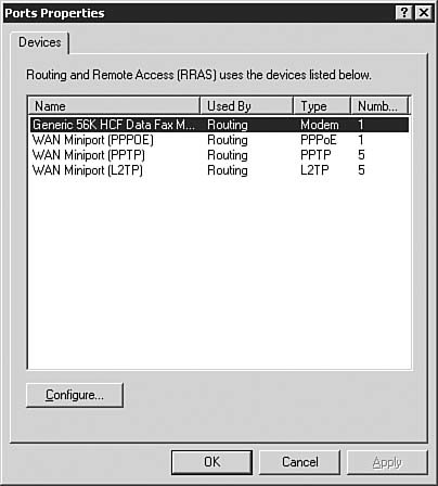
Figure 7.27. The Configure Device screen allows you to determine the function of a port. 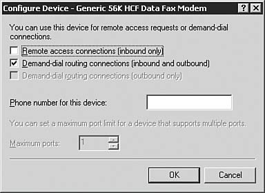
| | | 4. | Select Demand-Dial Routing Connections (Inbound and Outbound). This makes the port available to participate in routing. You would use the other parameters on the Configure Device screen if the server were going to be used as a remote access server/dial-in server, which is beyond the scope for this exercise. Click OK to assign this port for use with demand-dial router connections. Click OK to return to the Routing and Remote Access console.
| | | 5. | To check the status of the port, click the Ports icon in the Routing and Remote Access console. Each available port is displayed. Double-click the modem you configured in Steps 3 and 4. The Port Status screen appears, as seen in Figure 7.28. The Port Status screen displays a lot of useful statistics when a session is in progress, including how long the connection has been up, how much traffic has passed across the line, and the session addressing information.
Figure 7.28. The Port Status screen provides granular status on the various parameters associated with a port. 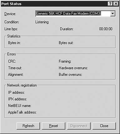
| 6. | Select Close to return to the Routing and Remote Access console.
|
Challenge You are the system and network administrator of Nounsense Publishing, a small business that is interested in connecting offices and getting on the Internet. The main headquarters of the company is in Boston, and there is a two-employee sales office in San Francisco. You have been asked by the company owner to connect the offices as inexpensively as possible, as well as set up an Internet connection. You would like to use a demand-dial connection for the small sales office and a dedicated Internet connection that will allow you to assign each of the workstations on the network a TCP/IP address that will identify it on the Internet. You currently have only one network segment in the corporate headquarters and a second in the San Francisco office. Your Internet connection must be online at all times, and you would like to minimize the management that is necessary on your part. You believe that the network will grow within the next year, and you would like to ensure that this can occur with a minimum of configuration. Through your discussions with the key stakeholders in this project, you've determined the following additional information: There must be a dedicated connection to the Internet. There are two locations that need to be connected. The network may expand in the future, and that should occur with a minimum of configuration. At this time, there is only one segment on the network.
Your task is to implement the required routing solution for Nounsense Publishing. Try to complete this exercise on your own, listing your conclusions on a sheet of paper. After you have completed the exercise, compare your results to those given here. Answers When you're configuring a small office network, you can connect the office to the Internet in several ways. For instance, you can connect a small office network to the Internet via a demand-dial connection, or you can configure a router with Network Address Translation. However, based on the requirements of the scenario, the most appropriate solution is to implement a dedicated connection. You can connect the small office by using an ISDN or fractional T-1 line. Because you would like to minimize the configuration that is required, you should create a configuration based on either static routes or RIP. In this type of scenario, OSPF is much too complex a solution. To determine whether to use static routes or RIP, you must look closely at the requirements. Because the network may expand in the future and it should occur with a minimum of configuration, it is best to use a dynamic routing protocol that can adapt to a change in the network topology. Therefore, you should use RIP rather than static routing. |
Troubleshooting and Monitoring IP Routing Up to this point, this chapter discusses the theory behind routing protocols and explores the individual routing protocols. The following sections focus on some of the other tools that can be used in a network environment to help configure routing and to troubleshoot routing problems, including some troubleshooting options for each of the routing protocols. Using Network Monitor Network Monitor is a tool you can use to capture network traffic. It can be used to diagnose problems when two computers do not communicate with one another or when a computer has trouble functioning in a network environment. For instance, a computer may have problems resolving names or finding a path to another computer (that is, it has routing problems). Network Monitor can be configured to capture network traffic in several ways. It can be configured to capture all network traffic that it receives, to respond to events on the network, or to monitor only a subset of the traffic (for instance, a particular protocol, such as HTTP traffic only). After the network data has been captured, Network Monitor analyzes the data and translates it into its logical frame structure to make the protocol information readable to the person capturing the information. Each frame contains the following: Exam Alert: Network Analysis Analyzing the traffic you see in Network Monitor is not only well beyond the scope of this book, but also cannot be tested on the exam. Network analysis is a science that takes a good deal of training and experience to master. For the exam, you should just be aware that Network Monitor gives you the capability to capture and analyze packets.
The source address of the computer that is sending the frame The destination address of the computer that received the frame Headers from each protocol used to send the frame The data or a portion of the information being sent
After the data has been translated, the information is presented through the graphical display provided by Network Monitor. Figure 7.29 shows an example of what the data looks like after it has been captured. Figure 7.29. Network Monitor gives a lot of information about the traffic on a network. 
Supporting Windows Server 2003 Routing As a network administrator, you have the task of configuring and installing RRAS. After RRAS is configured and installed, you are then responsible for managing additional changes to the existing configuration, monitoring the installed configuration for problems, and troubleshooting problems when they arise. RRAS Operation After you have configured RRAS, you can perform several tasks to manage its ongoing operation. Some of the items you need to manage and monitor include the following: Administer a remote router. Check the status of existing interfaces. View existing routing tables and verify that routes are being received from routing protocols. Determine the status of RRAS services and reset the services, if required.
In most large companies, users, systems, and services can be located in multiple locations throughout the country (or even the world). Coupled with the centralization of information technology resources, this can present problems for managing remote installations. With RRAS, it is possible to remotely manage RRAS routers from a central location. The RRAS console allows you to quickly determine whether the existing interfaces are active. In addition to monitoring the event logs for possible messages that indicate problems, you can also check the individual interfaces to see what their operational states are. Even if you have determined that the interfaces for a particular server are operational, it's still possible that the existing interfaces are not receiving routes to update the routing tables. You, as an administrator, would like to determine whether the router is indeed receiving updates. Again, the RRAS console provided with Windows Server 2003 allows you to do this. To view the routing tables of a particular protocol, within the Routing and Remote Access console, select and expand the server and the IP Routing head, and then select Static Routes. Then right-click Static Routes and select the Show IP Routing Table option. You can then verify whether the router is receiving updates to its routing table from other routers in the network. Finally, you might want to check the overall status of the services to determine whether they are running. If they are not running, you need to start them by choosing Computer Management, selecting Services and Applications, and then selecting Services. In the left pane of the Routing and Remote Access console, you need to verify that the Status column displays Started. If the service is not started, you should right-click Routing and Remote Access, and then click Start. If the router does not start, you should check the system event log for error messages. Troubleshooting RIP Environments After RIP is configured within your environment, you might be called on from time to time to troubleshoot problems that arise with routing. Although every problem is unique, Table 7.2 outlines some of the solutions that might help when you're responding to problems in a RIP environment. Table 7.2. RIP Problems, Potential Causes, and Possible SolutionsProblem | Cause/Solution |
|---|
Routing tables have improper routing information in a mixed RIP network. | RIPv2 routers are configured to multicast announcements. Multicast RIPv1 and RIPv2 announcements are never received by RIPv1 routers. If you have a mixed environment of RIPv1 and RIPv2, you need to ensure that the routers configured with RIPv2 use broadcast instead of multicast announcements. | Silent RIP hosts are not receiving routes. | RIPv2 routers are configured to multicast announcements. Multicast announcements are never received by silent RIP hosts. If silent RIP hosts on a network are not receiving routes from the local RIP router, you need to verify the version of RIP supported by the silent RIP hosts. If it is the listening service in Windows NT 4.0 Service Pack 4 or Windows Server 2003, you must configure the RIP routers for RIPv1 or RIPv2 broadcasting. | RIP routers are not being updated with valid routes. | You may be deploying variable- length subnetting, disjointed subnets, or supernetting in a RIPv1 or mixed RIPv1 and RIPv2 environment. You should not deploy variable-length subnetting, disjointed subnets, or supernetting in a RIPv1 or mixed RIPv1 and RIPv2 environment because it is not supported. | Host or default routes are not being propagated. | By default, RIP is not configured to propagate host or default routes. If these need to be propagated, you should change the default settings on the Advanced tab of the Properties dialog box of a RIP interface. |
The problems described in Table 7.2 are only some of the ones that can arise in a RIP environment. For further troubleshooting information, refer to Microsoft TechNet or the Windows Server 2003 documentation. Troubleshooting OSPF Environments OSPF is a more complex protocol to understand than RIP. Therefore, there is more risk of problems arising because of the complexity of the protocol. The fact that OSPF is more hierarchical than other protocols offers an opportunity to help troubleshoot problems that may arise; you can isolate issues to a particular area or the interconnectivity between areas. Problems and their possible solutions include those shown in Table 7.3. Table 7.3. OSPF Problems, Potential Causes, and Possible SolutionsProblem | Cause/Solution |
|---|
OSPF adjacency is not forming between two neighbors. | OSPF is not enabled on the interface. You should verify that OSPF is enabled on the interface on the network segment where an adjacency should form. By default, when you add an interface to the OSPF routing protocol, OSPF is disabled for the interface and must be manually enabled. | | | If OSPF is enabled, you should try to ping the neighboring router to ensure basic IP and network connectivity. You can use the tracert command to trace the route to the neighboring router. There should not be any routers between the neighboring routers. | A virtual link is not forming between two areas. | There may be a mismatched configuration of password, hello interval, or dead interval. You should verify that the virtual link neighbor routers are configured for the same password, hello interval, and dead interval. | | | Another possible cause is that virtual link neighbors may be configured for the incorrect transit area ID. You should verify that both virtual link neighbors are configured for the same transit area ID and that they are configured to use the correct transit area. | Routing tables are not being updated with OSPF routes or improper OSPF routes are being received. | You may not be receiving summarized routes. If you are not receiving summarized OSPF routes for an area, you should verify that the area border routers for the area are configured with the proper destination/network mask pairs summarizing that area's routes. | | | Another potential cause is that all area border routers are not connected to the backbone. You should verify that all area border routers are either physically connected to the backbone or logically connected to the backbone by using border routers, which are routers that connect two areas without going through the backbone. |
Table 7.3 lists only some of the problems that can arise in an OSPF environment. For further troubleshooting information, refer to Microsoft Technet or the Windows Server 2003 documentation. |