24.2 Path MTU Discovery
24.2 Path MTU Discovery
In Section 2.9 we described the concept of the path MTU. It is the minimum MTU on any network that is currently in the path between two hosts . Path MTU discovery entails setting the "don't fragment" (DF) bit in the IP header to discover if any router on the current path needs to fragment IP datagrams that we send. In Section 11.6 we showed the ICMP unreachable error returned by a router that is asked to forward an IP datagram with the DF bit set when the MTU is less than the datagram size . In Section 11.7 we showed a version of the traceroute program that used this mechanism to determine the path MTU to a destination. In Section 11.8 we saw how UDP handled path MTU discovery. In this section we'll examine how this mechanism is used by TCP, as specified by RFC 1191 [Mogul and Deering 1990].
Of the various systems used in this text (see the Preface) only Solaris 2.x supports path MTU discovery.
TCP's path MTU discovery operates as follows . When a connection is established, TCP uses the minimum of the MTU of the outgoing interface, or the MSS announced by the other end, as the starting segment size. Path MTU discovery does not allow TCP to exceed the MSS announced by the other end. If the other end does not specify an MSS, it defaults to 536. It is also possible for an implementation to save path MTU information on a per-route basis, as we mentioned in Section 21.9.
Once the initial segment size is chosen , all IP datagrams sent by TCP on that connection have the DF bit set. If an intermediate router needs to fragment a datagram that has the DF bit set, it discards the datagram and generates the ICMP "can't fragment" error we described in Section 11.6.
If this ICMP error is received, TCP decreases the segment size and retransmits. If the router generated the newer form of this ICMP error, the segment size can be set to the next-hop MTU minus the sizes of the IP and TCP headers. If the older ICMP error is returned, the probable value of the next smallest MTU (Figure 2.5) must be tried. When a retransmission caused by this ICMP error occurs, the congestion window should not change, but slow start should be initiated.
Since routes can change dynamically, when some time has passed since the last decrease of the path MTU, a larger value (up to the minimum of the MSS announced by the other end, or the outgoing interface MTU) can be tried. RFC 1191 recommends this time interval be about 10 minutes. (We saw in Section 11.8 that Solaris 2.2 uses a 30-second timer for this.)
Given the normal default MSS of 536 for nonlocal destinations, path MTU discovery avoids fragmentation across intermediate links with an MTU of less than 576 (which is rare). It can also avoid fragmentation on local destinations when an intermediate link (e.g., an Ethernet) has a smaller MTU than the end-point networks (e.g., a token ring). But for path MTU discovery to be more useful, and take advantage of wide area networks with MTUs greater than 576, implementations must stop using a default MSS of 536 bytes for nonlocal destinations. A better choice for the MSS is the MTU of the outgoing interface (minus the size of the IP and TCP headers, of course). (In Appendix E we'll see that most implementations allow the system administrator to change this default MSS value.)
An Example
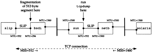
We can see how path MTU discovery operates when an intermediate router has an MTU less than either of the end point's interface MTUs. Figure 24.1 shows the topology for this example.
Figure 24.1. Topology for path MTU example.

We'll establish a connection from the host solaris (which supports the path MTU discovery mechanism) to the host slip. This setup is identical to the one used for our UDP path MTU discovery example (Figure 11.13) but here we have set the MTU of the interface on slip to 552, instead of its normal 296. This causes slip to announce an MSS of 512. But leaving the MTU of the SLIP link on bsdi at 296 will cause TCP segments greater than 256 to be fragmented , and we can see how the path MTU discovery mechanism on solaris handles this.
We'll run our sock program on solaris and perform one 512-byte write to the discard server on slip:
solaris % sock -i -n1 -w512 slip discard
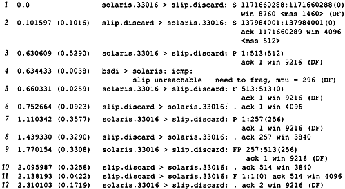
Figure 24.2 shows the tcpdump output, collected on the SLIP interface on the host sun.
Figure 24.2. tcpdump output for path MTU discovery.

The MSS values in lines 1 and 2 are what we expect. We then see solaris send a 512-byte segment (line 3) containing the 512 bytes of data and the ACK of the SYN. (We saw this combination of the ACK of a SYN along with the first segment of data in Exercise 18.9.) This generates the ICMP error in line 4 and we see that the router bsdi generates the newer ICMP error containing the MTU of the outgoing interface.
It appears that before this error makes it back to solaris, the FIN is sent (line 5). Since slip never received the 512 bytes of data discarded by the router bsdi, it is not expecting this sequence number (513), so it responds in line 6 with the expected sequence number (1).
At this time the ICMP error has made it back to solaris and it retransmits the 512 bytes of data in two 256-byte segments (lines 7 and 9). Both are sent with the DF bit set, since there could be another router beyond bsdi with a smaller MTU.
A longer transfer was run (taking about 15 minutes) and after moving from the 512-byte initial segment to 256-byte segments, solaris never tried the higher segment size again.
Big Packets or Small Packets?
Conventional wisdom says that bigger packets are better [Mogul 1993, Sec. 15.2.8] because sending fewer big packets "costs less" than sending more smaller packets. (This assumes the packets are not large enough to cause fragmentation, since that introduces another set of problems.) The reduced cost is that associated with the network (packet header overhead), routers (routing decisions), and hosts (protocol processing and device interrupts). Not everyone agrees with this [Bellovin 1993].
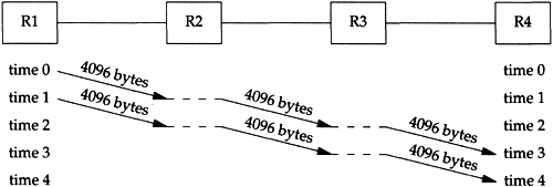
Consider the following example. We send 8192 bytes through four routers, each connected with a T1 telephone line (1,544,000 bits/sec). First we use two 4096-byte packets, as shown in Figure 24.3.
Figure 24.3. Sending two 4096-byte packets through four routers.

The basic problem is that routers are store-and-forward devices. They normally receive the entire input packet, validate the IP header including the IP checksum, make their routing decision, and start sending the output packet. In this figure we're assuming the ideal case where it takes no time for these operations to occur at the router (the horizontal dashed lines). Nevertheless, it takes four units of time to send all 8192 bytes from R1 to R4. The time for each hop is

(We account for the 40 bytes of IP and TCP header.) The total time to send the data is the number of packets plus the number of hops, minus one, which we can see visually in this example is four units of time, or 85.6 ms. Each link is idle for two units of time, or 42.8 ms.
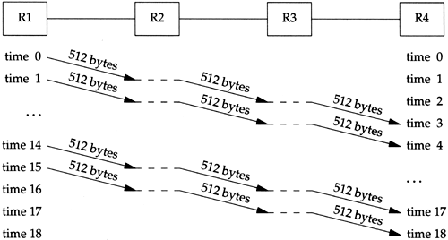
Figure 24.4 shows what happens if we send sixteen 512-byte packets.
Figure 24.4. Sending sixteen 512-byte packets through four routers.

It takes more units of time, but the units are shorter since a smaller packet is being sent.

The total time is now (18 — 2.9) = 52.2 ms. Each link is again idle for two units of time, which is now 5.8 ms.
In this example we have ignored the time required for the ACKs to be returned, the connection establishment and termination times, and the possible sharing of the links with other traffic. Nevertheless, measurements in [Bellovin 1993] indicate that bigger is not always better. More research is required in this area on various networks.
EAN: 2147483647
Pages: 378