20.7 Bulk Data Throughput
20.7 Bulk Data Throughput
Let's look at the interaction of the window size , the windowed flow control, and slow start on the throughput of a TCP connection carrying bulk data.
Figure 20.9 shows the steps over time of a connection between a sender on the left and a receiver on the right. Sixteen units of time are shown. We show only discrete units of time in this figure, for simplicity. We show segments carrying data going from the left to right in the top half of each picture, numbered 1, 2, 3, and so on. The ACKs go in the other direction in the bottom half of each picture. We draw the ACKs smaller, and show the segment number being acknowledged .
Figure 20.9. Times 0 “15 for bulk data throughput example.
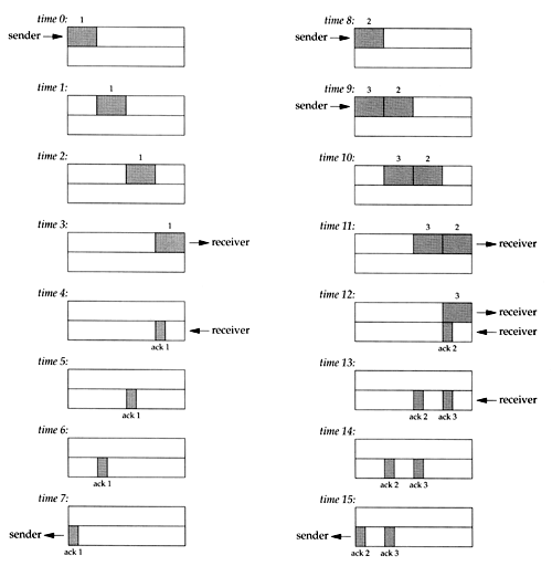
At time 0 the sender transmits one segment. Since the sender is in slow start (its congestion window is one segment), it must wait for the acknowledgment of this segment before continuing.
At times 1, 2, and 3 the segment moves one unit of time to the right. At time 4 the receiver reads the segment and generates the acknowledgment. At times 5, 6, and 7 the ACK moves to the left one unit, back to the sender. We have a round-trip time (RTT) of 8 units of time.
We have purposely drawn the ACK segment smaller than the data segment, since it's normally just an IP header and a TCP header. We're showing only a unidirectional flow of data here. Also, we assume that the ACK moves at the same speed as the data segment, which isn't always true.
In general the time to send a packet depends on two factors: a propagation delay (caused by the finite speed of light, latencies in transmission equipment, etc.) and a transmission delay that depends on the speed of the media (how many bits per second the media can transmit). For a given path between two nodes the propagation delay is fixed while the transmission delay depends on the packet size. At lower speeds the transmission delay dominates (e.g., Exercise 7.2 where we didn't even consider the propagation delay), whereas at gigabit speeds the propagation delay dominates (e.g., Figure 24.6).
When the sender receives the ACK it can transmit two more segments (which we've numbered 2 and 3), at times 8 and 9. Its congestion window is now two segments. These two segments move right toward the receiver, where the ACKs are generated at times 12 and 13. The spacing of the ACKs returned to the sender is identical to the spacing of the data segments. This is called the self-clocking behavior of TCP. Since the receiver can only generate ACKs when the data arrives, the spacing of the ACKs at the sender identifies the arrival rate of the data at the receiver. (In actuality, however, queueing on the return path can change the arrival rate of the ACKs.)
Figure 20.10 shows the next 16 time units. The arrival of the two ACKs increases the congestion window from two to four segments, and these four segments are sent at times 16 “19. The first of the ACKs returns at time 23. The four ACKs increase the congestion window from four to eight segments, and these eight segments are transmitted at times 24 “31.
Figure 20.10. Times 16 “31 for bulk data throughput example.
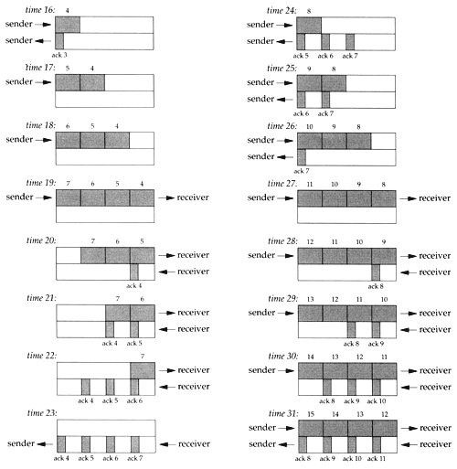
At time 31, and at all successive times, the pipe between the sender and receiver is full. It cannot hold any more data, regardless of the congestion window or the window advertised by the receiver. Each unit of time a segment is removed from the network by the receiver, and another is placed into the network by the sender. However many data segments fill the pipe, there are an equal number of ACKs making the return trip. This is the ideal steady state of the connection.
Bandwidth-Delay Product
We can now answer the question: how big should the window be? In our example, the sender needs to have eight segments outstanding and unacknowledged at any time, for maximum throughput. The receiver's advertised window must be that large, since that limits how much the sender can transmit.
We can calculate the capacity of the pipe as
capacity (bits) = bandwidth (bits/sec) — round-trip time (sec)
This is normally called the bandwidth-delay product. This value can vary widely, depending on the network speed and the RTT between the two ends. For example, a T1 telephone line (1,544,000 bits/sec) across the United States (about a 60-ms RTT) gives a bandwidth-delay product of 11,580 bytes. This is reasonable in terms of the buffer sizes we talked about in Section 20.4, but a T3 telephone line (45,000,000 bits/sec) across the United States gives a bandwidth-delay product of 337,500 bytes, which is bigger than the maximum allowable TCP window advertisement (65535 bytes). We describe the new TCP window scale option in Section 24.4 that gets around this current limitation of TCP.
The value 1,544,000 bits/sec for a T1 phone line is the raw bit rate. The data rate is actually 1,536,000 bits/sec, since 1 bit in 193 is used for framing. The raw bit rate of a T3 phone line is actually 44,736,000 bits/sec, and the data rate can reach 44,210,000 bits/sec. For our discussion we'll use 1.544 Mbits/sec and 45 Mbits/sec.
Either the bandwidth or the delay can affect the capacity of the pipe between the sender and receiver. In Figure 20.11 we show graphically how a doubling of the RTT doubles the capacity of the pipe.
Figure 20.11. Doubling the RTT doubles the capacity of the pipe.
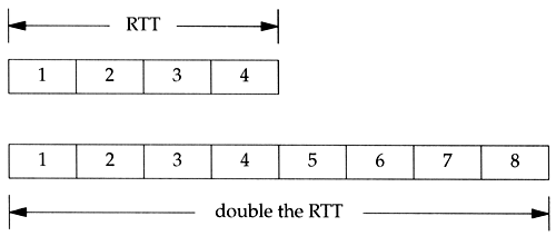
In the lower illustration of Figure 20.11, with the longer RTT, the pipe can hold eight segments, instead of four.
Similarly, Figure 20.12 shows that doubling the bandwidth also doubles the capacity of the pipe.
Figure 20.12. Doubling the bandwidth doubles the capacity of the pipe.
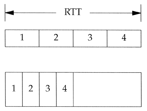
In the lower illustration of Figure 20.12, we assume that the network speed has doubled, allowing us to send four segments in half the time as in the top picture. Again, the capacity of the pipe has doubled . (We assume that the segments in the top half of this figure have the same area, that is the same number of bits, as the segments in the bottom half.)
Congestion
Congestion can occur when data arrives on a big pipe (a fast LAN) and gets sent out a smaller pipe (a slower WAN). Congestion can also occur when multiple input streams arrive at a router whose output capacity is less than the sum of the inputs.
Figure 20.13 shows a typical scenario with a big pipe feeding a smaller pipe. We say this is typical because most hosts are connected to LANs, with an attached router that is connected to a slower WAN. (Again, we are assuming the areas of all the data segments (9 “20) in the top half of the figure are the same, and the areas of all the acknowledgments in the bottom half are all the same.)
Figure 20.13. Congestion caused by a bigger pipe feeding a smaller pipe.
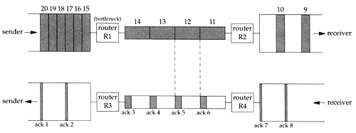
In this figure we have labeled the router R1 as the "bottleneck," because it is the congestion point. It can receive packets from the LAN on its left faster than they can be sent out the WAN on its right. (Commonly R1 and R3 are the same router, as are R2 and R4, but that's not required; asymmetrical paths can occur.) When router R2 puts the received packets onto the LAN on its right, they maintain the same spacing as they did on the WAN on its left, even though the bandwidth of the LAN is higher. Similarly, the spacing of the ACKs on their way back is the same as the spacing of the slowest link in the path.
In Figure 20.13 we have assumed that the sender did not use slow start, and sent the segments we've numbered 1 “20 as fast as the LAN could take them. (This assumes the receiving host advertised a window of at least 20 segments.) The spacing of the ACKs will correspond to the bandwidth of the slowest link, as we show. We are assuming the bottleneck router has adequate buffering for all 20 segments. This is not guaranteed , and can lead to that router discarding packets. We'll see how to avoid this when we talk about congestion avoidance in Section 21.6.
EAN: 2147483647
Pages: 378