11.5 IP Fragmentation
11.5 IP Fragmentation
As we described in Section 2.8, the physical network layer normally imposes an upper limit on the size of the frame that can be transmitted. Whenever the IP layer receives an IP datagram to send, it determines which local interface the datagram is being sent on (routing), and queries that interface to obtain its MTU. IP compares the MTU with the datagram size and performs fragmentation, if necessary. Fragmentation can take place either at the original sending host or at an intermediate router.
When an IP datagram is fragmented , it is not reassembled until it reaches its final destination. (This handling of reassembly differs from some other networking protocols that require reassembly to take place at the next hop, not at the final destination.) The IP layer at the destination performs the reassembly. The goal is to make fragmentation and reassembly transparent to the transport layer (TCP and UDP), which it is, except for possible performance degradation. It is also possible for the fragment of a datagram to again be fragmented (possibly more than once). The information maintained in the IP header for fragmentation and reassembly provides enough information to do this.
Recalling the IP header (Figure 3.1), the following fields are used in fragmentation. The identification field contains a unique value for each IP datagram that the sender transmits. This number is copied into each fragment of a particular datagram. (We now see the use for this field.) The flags field uses one bit as the "more fragments " bit. This bit is turned on for each fragment comprising a datagram except the final fragment. The fragment offset field contains the offset (in 8-byte units) of this fragment from the beginning of the original datagram. Also, when a datagram is fragmented the total length field of each fragment is changed to be the size of that fragment.
Finally, one of the bits in the flags field is called the "don't fragment" bit. If this is turned on, IP will not fragment the datagram. Instead the datagram is thrown away and an ICMP error ("fragmentation needed but don't fragment bit set," Figure 6.3) is sent to the originator. We'll see an example of this error in the next section.
When an IP datagram is fragmented, each fragment becomes its own packet, with its own IP header, and is routed independently of any other packets. This makes it possible for the fragments of a datagram to arrive at the final destination out of order, but there is enough information in the IP header to allow the receiver to reassemble the fragments correctly.
Although IP fragmentation looks transparent, there is one feature that makes it less than desirable: if one fragment is lost the entire datagram must be retransmitted. To understand why this happens, realize that IP itself has no timeout and retransmission ”that is the responsibility of the higher layers . (TCP performs timeout and retransmission, UDP doesn't. Some UDP applications perform timeout and retransmission themselves .) When a fragment is lost that came from a TCP segment, TCP will time out and retransmit the entire TCP segment, which corresponds to an IP datagram. There is no way to resend only one fragment of a datagram. Indeed, if the fragmentation was done by an intermediate router, and not the originating system, there is no way for the originating system to know how the datagram was fragmented. For this reason alone, fragmentation is often avoided. [Kent and Mogul 1987] provide arguments for avoiding fragmentation.
Using UDP it is easy to generate IP fragmentation. (We'll see later that TCP tries to avoid fragmentation and that it is nearly impossible for an application to force TCP to send segments large enough to require fragmentation.) We can use our sock program and increase the size of the datagram until fragmentation occurs. On an Ethernet the maximum amount of data in a frame is 1500 bytes (Figure 2.1), which leaves 1472 bytes for our data, assuming 20 bytes for the IP header and 8 bytes for the UDP header. We'll run our sock program, with data sizes of 1471, 1472, 1473, and 1474 bytes. We expect the last two to cause fragmentation:
bsdi % sock -u -i -n1 -w1471 svr4 discard bsdi % sock -u -i -n1 -w1472 svr4 discard bsdi % sock -u -i -n1 -w1473 svr4 discard bsdi % sock -u -i -n1 -w1474 svr4 discard
Figure 11.7 shows the corresponding tcpdump output.
Figure 11.7. Watching fragmentation of UDP datagrams.
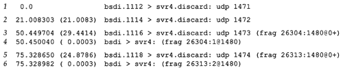
The first two UDP datagrams (lines 1 and 2) fit into Ethernet frames , and are not fragmented. But the length of the IP datagram corresponding to the write of 1473 bytes is 1501, which must be fragmented (lines 3 and 4). Similarly the datagram generated by the write of 1474 bytes is 1502, and is also fragmented (lines 5 and 6).
When the IP datagram is fragmented, tcpdump prints additional information. First, the output frag 26304 (lines 3 and 4) and frag 26313 (lines 5 and 6) specify the value of the identification field in the IP header.
The next number in the fragmentation information, the 1480 between the colon and the at sign in line 3, is the size, excluding the IP header. The first fragment of both datagrams contains 1480 bytes of data: 8 bytes for the UDP header and 1472 bytes of user data. (The 20-byte IP header makes the packet exactly 1500 bytes.) The second fragment of the first datagram (line 4) contains 1 byte of data ”the remaining byte of user data. The second fragment of the second datagram (line 6) contains the remaining 2 bytes of user data.
Fragmentation requires that the data portion of the generated fragments (that is, everything excluding the IP header) be a multiple of 8 bytes for all fragments other than the final one. In this example, 1480 is a multiple of 8.
The number following the at sign is the offset of the data in the fragment, from the start of the datagram. The first fragment of both datagrams starts at 0 (lines 3 and 5) and the second fragment of both datagrams starts at byte offset 1480 (lines 4 and 6). The plus sign following this offset that is printed for the first fragment of both datagrams means there are more fragments comprising this datagram. This plus sign corresponds to the "more fragments" bit in the 3-bit flags in the IP header. The purpose of this bit is to let the receiver know when it has completed the reassembly of all the fragments for a datagram.
Finally, notice that lines 4 and 6 (fragments other than the first) omit the protocol (UDP) and the source and destination ports. The protocol could be printed, since it's in the IP header that's copied into the fragments. The port numbers , however, are in the UDP header, which only occurs in the first fragment.
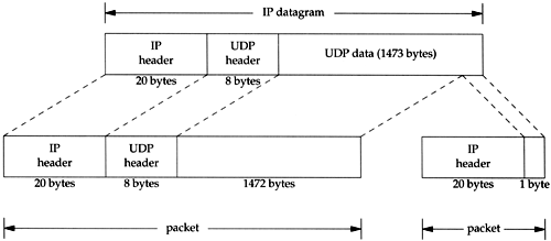
Figure 11.8 shows what's happening with the third datagram that is sent (with 1473 bytes of user data). It reiterates that any transport layer header appears only in the first fragment.
Figure 11.8. Example of UDP fragmentation.
Also note the terminology: an IP datagram is the unit of end-to-end transmission at the IP layer (before fragmentation and after reassembly), and a packet is the unit of data passed between the IP layer and the link layer. A packet can be a complete IP datagram or a fragment of an IP datagram.
EAN: 2147483647
Pages: 378
- Chapter III Two Models of Online Patronage: Why Do Consumers Shop on the Internet?
- Chapter V Consumer Complaint Behavior in the Online Environment
- Chapter VIII Personalization Systems and Their Deployment as Web Site Interface Design Decisions
- Chapter IX Extrinsic Plus Intrinsic Human Factors Influencing the Web Usage
- Chapter XIV Product Catalog and Shopping Cart Effective Design