Fast Ethernet: 100BaseT
| |
The idea of Fast Ethernet was first proposed in 1992. In August 1993, a group of vendors came together to form the Fast Ethernet Alliance (FEA). The goal of the FEA was to speed Fast Ethernet through the Institute of Electrical and Electronic Engineers (IEEE) 802.3 body, the committee that controls the standards for Ethernet. Fast Ethernet and the FEA succeeded, and in June 1995, the technology passed a full review and was formally assigned the name 802.3u.
The IEEE's name for Fast Ethernet is 100BaseT, and the reason for this name is simple: 100BaseT is an extension of the 10BaseT standard, designed to raise the data transmission capacity of 10BaseT from 10Mbits/sec to 100Mbits/sec. An important strategy incorporated by 100BaseT is its use of the Carrier Sense Multiple Access with Collision Detection (CSMA/CD) protocolwhich is the same protocol that 10BaseT usesbecause of its ability to work with several different types of cable, including basic twisted-pair wiring. Both of these features play an important role in business considerations, and they make 100BaseT an attractive migration path for those networks based on 10BaseT.
The basic business argument for 100BaseT resides in the fact that Fast Ethernet is a legacy technology. Because it uses the same transmission protocol as older versions of Ethernet and is compatible with the same types of cable, less capital investment will be needed to convert an Ethernet-based network to Fast Ethernet than to other forms of high-speed networking. Also, because 100BaseT is a continuation of the old Ethernet standard, many of the same network analysis tools, procedures, and applications that run over the old Ethernet network work with 100BaseT. Consequently, managers experienced at running an Ethernet network should find the 100BaseT environment familiar, meaning less time and money must be spent by the company on training.
Protocol Preservation
Perhaps the shrewdest strategy taken with Fast Ethernet was the decision to leave the transmission protocol intact. The transmission protocol, in this case CSMA/CD, is the method a network uses to transmit data from one node to another, over the cable. In the OSI model, CSMA/CD is part of the Media Access Control, or MAC, layer. The MAC layer specifies how information is formatted for transmission and the way in which a network device gains access to, or control of, a network for transmission.
The name CSMA/CD can be broken down into two parts : Carrier Sense Multiple Access and Collision Detection. The first part of the name describes how a node equipped with a network adapter determines the appropriate time to send a transmission. In CSMA, a network node first "listens" to the wire to find out if any other transmission is currently being broadcast over the network. If the node receives a carrier tone, which implies that the network is busy with another transmission, it holds onto its transmission and waits until the network is clear. When it does sense a quiet network, it begins its transmission. The broadcast is actually sent to all nodes on the network segment, but only the node with the correct address accepts the transmission.
The Collision Detection feature is meant to remedy situations in which two or more nodes inadvertently broadcast a transmission at the same time. Under the CSMA structure, any node that is ready to transmit first listens to determine whether the network is free. If two nodes were to listen at the exact same moment, however, both would perceive the network to be free and both would transmit their packets simultaneously . In this situation, the transmissions would interfere with each other (network engineers call this a collision) and neither would reach its destination intact. Thanks to Collision Detection, a node will listen to the line again after it has broadcast its packet. If it detects a collision, it waits a random period of time and rebroadcasts the transmission, again listening for a collision.
Three Kinds Of Fast
Another important consideration, along with the adoption of the CSMA/CD protocol, was the decision to design 100BaseT so it uses many basic forms of cablingthose used by older versions of Ethernet and newer forms of cabling, as well. To accommodate the different types of cables, Fast Ethernet comes in three forms: 100BaseTX, 100BaseT4, and 100BaseFX. Both 100BaseTX and 100BaseT4 work with twisted-pair cabling standards, while 100BaseFX was created to work with fiber optic cabling.
The 100BaseTX standard is compatible with two pairs of UTP or STP. One pair is designated for reception and the other for transmission. The two basic cabling standards that meet this requirement are EIA/TIA-568 Category 5 UTP and IBM's Type 1 STP. The attractiveness of 100BaseTX lies in its ability to provide full-duplex performance with network servers and the fact that it uses only two of the four pairs of wiring, leaving two pairs free for future enhancements to your network.
However, if you plan on using Category 5 cabling with 100BaseTX, be forewarned of the drawbacks related to Category 5. The cable is more expensive than other types of four-pair cabling, such as Category 3, and it requires the installation of punchdown blocks, connectors, and patch panels that are all Category 5-compliant.
The 100BaseT4 standard requires a less sophisticated cable than Category 5. The reason is that 100BaseT4 uses four pairs of wiring: one for transmission, one for reception, and two that can either transmit or receive data. Therefore, 100BaseT4 has the use of three pairs of wiring to either transmit or receive data. By dividing up the 100Mbit/sec data signal among the three pairs of wiring, 100BaseT4 reduces the average frequency of signals on the cable, allowing lower-quality cable to handle the signal successfully. Categories 3 and 4 UTP cabling, as well as Category 5 UTP and Type 1 STP, can all work in 100BaseT4 implementations .
The advantage of 100BaseT4 is its flexible cable requirements. Category 3 and 4 cabling was once more prevalent in existing networks, and if they aren't already being used in your network, they cost less than Category 5 cabling. The downside is that 100BaseT4 uses all four pairs of wiring, and it does not support full-duplex operation.
Fast Ethernet also offers a standard for operation over multimode fiber with a 62.5 micron core and 125 micron cladding. The 100BaseFX standard is designed mainly for backbone use, connecting Fast Ethernet repeaters scattered about the building. The traditional benefits of fiber optic cabling are still valid with 100BaseFX: protection from electromagnetic noise, increased security, and longer distances allowed between network devices.
The Short Run
Although Fast Ethernet is a continuation of the Ethernet standard, the migration from a 10BaseT network to a 100BaseT network isn't a straight, one-to-one conversion of hardwaresome changes to the network topology may be required.
Theoretically, Fast Ethernet limits the end-to-end network diameter or the network segment diameter to 250 meters; only 10 percent of the 2,500-meter maximum theoretical size of Ethernet. Fast Ethernet's restriction is based on the speed of 100Mbit/sec transmission and the nature of the CSMA/CD protocol. Figure 1, Figure 2, and Figure 3 illustrate why a 100BaseT network can't be longer than 250 meters . In the figures, Workstations A and B represent the farthest ends of the network or network segment.
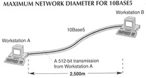
Figure 1: In traditional 10Mbps Ethernet networks, the maximum distance between two end stations is 2,500 meters.
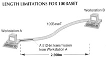
Figure 2: The maximum length limitation for 100BaseT is 250 meters, only 10 percent of the 2,500-meter maximum theoretical size of Ethernet.

Figure 3: Because of the increased throughput capabilities of 100BaseT, workstations A and B can be no farther than 250 meters apart.
For Ethernet to work, a workstation transmitting data must listen long enough to make sure the data has reached its destination safely. In a 10Mbit/sec Ethernet network, such as 10Base5, the length of time a workstation listens for a collision is equivalent to how far a 512-bit frame (the frame size is specified in the Ethernet standard) travels before the workstation is finished processing it. In a 10Mbit/sec Ethernet network, that distance is 2,500 meters (see Figure 1). However, a 512-bit frame (the 802.3u standard specifies the same frame size, 512 bit, as the 802.3 standard) being transmitted by a workstation in the faster 100Mbit/sec Ethernet network travels only about 250 meters before the workstation is finished processing it (see Figure 2). If the receiving workstation was located farther than 250 meters from the transmitting workstation, the frame may collide with another frame down the line, and the transmitting workstation, having finished processing the transmission already, would not be listening for the collision. For this reason, the maximum network diameter for a 100BaseT network is 250 meters (see Figure 3).
To take advantage of the 250 meters, though, you will need to install two repeaters to connect all of the nodes. And, a node cannot be located farther than 100 meters away from a repeaterFast Ethernet adopted the 10BaseT rule that determines 100 meters to be the farthest allowable distance a workstation can be from a hub. Due to latency introduced by connection devices such as repeaters, the actual operational distances between nodes will probably prove to be less than those stated. So, it would be prudent to measure distances on the short side.
To incorporate longer runs in your network, you'll have to invest in fiber cabling. For example, you can use 100BaseFX in half-duplex mode to connect a switch to either another switch or an end station located up to 450 meters away. A full-duplex 100BaseFX installation will allow two network devices up to two kilometers apart to communicate.
A Simple Setup
Aside from the cabling, you'll need to deal with network adapters in workstations and servers, 100BaseT hubs, and possibly some 100BaseT switches.
The adapters you'll need for a Fast Ethernet network are called 10/100Mbit/sec Ethernet adapters. These adapters take advantage of an autosensing featureprovided for in the 100BaseT standardthat allows the adapters to automatically sense 10Mbit/sec and 100Mbit/sec speed capabilities. You'll also need to install a 100BaseT hub to service the group of workstations and servers you've converted to 100BaseT.
When a PC or server equipped with a 10/100 adapter is turned on, it will emit a signal that broadcasts its 100Mbit/sec capabilities. If the receiving station, most likely a hub, is similarly suited for 100BaseT operation, it will return a signal that automatically places both the hub and PC or server in 100BaseT mode. If the hub is only 10BaseT-capable, it won't return the signal, and the PC or server will automatically go into 10BaseT mode.
For a small-scale 100BaseT setup, you can use a 10/100 bridge or switch to allow the 100BaseT part of your network to operate with the 10BaseT installed base.
Deceptive Speed
As a last piece of advice, Fast Ethernet's capabilities seem best suited for peak traffic problems. For example, if you have some users running CAD or imaging applications who need to have a higher peak throughput, Fast Ethernet can help you out. But, if your problem is caused by an overload of users, 100BaseT starts to drag at about the 50-percent utilization ratein other words, at the same traditional threshold as 10BaseT. After all, it is an extension of 10BaseT.
This tutorial, number 88, by Lee Chae, was originally published in the December 1995 issue of LAN Magazine/Network Magazine.
| |
EAN: 2147483647
Pages: 193
- ERP Systems Impact on Organizations
- Challenging the Unpredictable: Changeable Order Management Systems
- ERP System Acquisition: A Process Model and Results From an Austrian Survey
- A Hybrid Clustering Technique to Improve Patient Data Quality
- Relevance and Micro-Relevance for the Professional as Determinants of IT-Diffusion and IT-Use in Healthcare