Non-Volatile Storage
| | ||
| | ||
| | ||
Storage media are at the heart of most computer forensics cases. In many cases, data in-transit cannot be obtained, or historical data (for example, a suspect's email messages sent last June) is needed as part of the investigation. The majority of a computer investigator 's analysis time is likely to be spent imaging, analyzing, and reporting information uncovered from storage devices.
The present-day storage landscape is complex. Information can be stored in many forms, on many different devices. Traditional storage media can be grouped into two categories: removable media and non-removable media. Removable media includes floppy disks, CD-ROMs, DVDs, Zip disks, and magnetic tapes. Non-removable media primarily refers to hard disks.
Traditional media (both removal and non-removable) use one of two primary technologies: optical data storage or magnetic data storage. Optical data storage devices use a laser to change read pits on a platter. Depending on the reflection/non-reflection of the light, each pit or lack thereof is read as a one or a zero by the computer. Writing to the media used by these devices generally occurs with a separate device used to press the pits in place or with a dye that changes properties (such as that used in CD-Rs) when a different wavelength or intensity of light is applied. Magnetic storage devices use an electromagnetic read/write head. The head is a sensor that either reads the charge present at a given location or changes the charge present at a given location.
In recent years , non-traditional storage media have made an appearance and are becoming more prevalent . USB-based flash drives , digital cameras with memory cards, and solid-state MP3 players all use different storage media. These devices can be used for their intended purpose or for general storage, and they will likely play a greater role in the future of computer investigations.
For a computer investigator, a basic understanding of each underlying storage technology is essential. When a sector-by-sector copy is made, the investigator should have a good understanding of what a sector is, how it relates to a cluster, and what is really being copied (and not copied ) when this occurs. The next sections introduce the basics behind the major storage technologies as they relate to a forensic examination.
Floppy Disks
The 1.44MB DS/HD 3.5-inch floppy disk remains one of the primary mechanisms for the transportation of data, despite its age, slow access speeds, and storage limitations. The floppy disk (of which the 3.5 inch is just the latest manifestation) is a platter-based magnetic-media storage technology encased in plastic. There were later versions of the 3.5-inch floppy, such as the 2.88MB and 120MB, and even 200MB attempts, but none became widely adopted.
| |
When performing a forensic acquisition of media, it is critical to ensure that no intentional or unintentional alteration of the data on that media occurs. When Windows mounts a device, it can actually write a signature to that device, thereby altering the contents slightly. Although not an insurmountable legal issue (the specific changes Windows makes can be replicated and demonstrated), any alteration is likely to create a hassle down to road. To prevent this, write blocking is used.
Write blocking ensures there can be no accidental writing on a given piece of media. Some media, such as the pressed and write-once formats of CD and DVD, are write-protected by design. After data is written, it cannot be overwritten or altered . Other media types like backup tapes, floppy disks, and USB flash drives may have a switch, tab, or window that allows write protection. This can and should be used when acquiring information from these media to ensure alteration does not occur.
Some media, including most hard disks, do not have built-in write protection. For the forensic examiner , this requires the use of software or hardware write blockers to ensure that the media is not altered.
Software-based write blockers trace their history to the DOS days, when they were able to intercept interrupts on drive access and prevent writing. Beyond Windows 95, these devices lost their effectiveness and are being replaced by new versions of software write blockers such as the forthcoming Fastbloc SE from Guidance Software. Software-based write blocking has been shown to be effective in lab environments but has not been broadly tested in the courts and has been conceptually questioned in academic literature. The promise of a technology-independent way to provide write blocking is enticing, but the computer investigator should evaluate any new software-based write blockers carefully before using them in a forensically sensitive case.
Hardware-based write blockers are more commonplace and sit between the device to be acquired and the analysis system. They use physical protection (for example, not connecting the write wires) to ensure that accidental writing does not occur and come with interfaces for most major media types, including SATA, IDE, and SCSI hard disks as well as flash-based media formats. The hardware write blockers then connect back to the analysis PC through the use of USB 2.0 or FireWire connections for quick transfers. The Ultrablock line from Digital Intelligence and the Fastbloc line from Guidance provide an array of write blockers that are broadly used, court tested, and proven effective. Every computer analysis lab should have one of these products (or its equivalent) to ensure that acquisitions are free of alterations.
| |
| Note | DS/HD refers to double sided (both sides of the disk are used for reading and writing) and high density (there are more bits per inch available). Older 3.5-inch 720KB disks were DS/DD (double sided/double density), with reduced storage available on each side. Their predecessors, 5.25-inch disks, were originally SS/SD (single sided/single density) and stored 180KB per side. Some original PC drives allowed that amount to be doubled by physically flipping over the floppy disk in the drive. |
The standard floppy disk consists of four major components :
-
Plastic casing . The plastic casing protects the floppy disk from dust and scratches and provides a rigid structure that can be placed inside a drive.
-
Metal slide window. The spring-loaded metal on the bottom of the floppy disk protects the platter when not in use. It retracts when placed in the floppy drive to allow the read/write head access to the underlying platter.
-
Cleaning-strip. Inside the plastic housing on most floppy disks is a cloth cleaning strip. The strip has light contact with the platter and permits the platter to be cleaned every rotation.
-
Platter. The platter is the heart of the floppy disk. It is a two-sided, coated disk that maintains a charge when applied by the read/write head. The platter is spun by a motor in the drive itself to store or retrieve information.
The floppy disk itself is placed into a floppy disk drive, which contains the digital logic circuitry , the drive motor, and the read/write head. To use the disk, the floppy drive spins the platter at around 300 revolutions per minute. The read/write head moves back and forth across the platter and operates on individual sectors of data within a rotational track as noted in Figure 3-2.
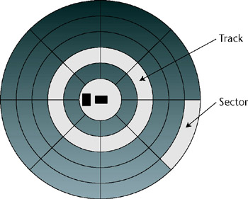
Figure 3-2: Disk platter layout
| Note | In reality, the sectors are not the same size . Smaller sectors are present on the inner areas and larger sectors on the outer to account for the increased space as well as the difference in speed as the head traverses them. |
Standard 3.5-inch floppy disks contain 80 tracks, with 18 sectors per track on each side of the platter. Each sector contains 512 bytes of usable information in addition to a basic preamble used by the read/write head for alignment and an error-correcting code to detect single and multi-bit errors on the disk. The only data directly accessible above the hardware layer is the sector data. A sector is likewise the smallest piece of information that can be read from or written to.
| Tip | The computer investigator might still encounter legacy 5.25-inch floppy disks. If they are encountered , legacy 5.25-inch 1.2MB drives can still be purchased online, or the suspect's drive may be acquired for the explicit purpose of reading them. |
Microsoft-formatted floppy disks use the FAT12 partition type, described later in the chapter, with a cluster size of 512 bytes. The cluster size is the smallest addressable space the operating system can read and write to and is made up of one or more sectors (one in the case of FAT12 floppy disks). Like all magnetic media, floppy disks degrade over time. Additionally, frequently used floppy disks can suffer from friction degradation. Unlike hard disks, the read/write head in a floppy drive actually rests on the platter. Over time, frequently used tracks might actually "burn-in" (visible as a white line around the disk) or individual sectors might become unreadable. When this occurs, standard operating system software may be unable to read the disk. Anadisk, specific to floppies and available from NTI, provides an easy-to-use mechanism to recover the remaining data on a disk with bad sectors for further analysis. This is one reason for slow transfer times on floppy disks. Higher rotational speeds would generate increased heat and degrade disks more quickly.
| |
Damaged floppy disks are not an uncommon thing for a computer investigator to encounter. In general, damage to any part of the disk (with the possible exception of gross damage to the platter) is something that can be recovered. Since floppy drives themselves are inexpensive, it is recommended that the investigator keep several drives laying around for "questionable" disks to prevent damage to one's regular floppy drive. Some possible situations of floppy damage and their solutions (short of using a Scanning Tunneling Microscope) are as follows :
-
Bent metal/non-retracting slide cover. If the metal becomes bent on a floppy disk, it might not fit in the drive, get stuck, or not retract to allow reading. The metal is just an added layer of protection, and the disk will function without it. To remove the metal slider, gently pull on the part of the metal closest to the center of the disk, bending it away from the plastic. Eventually, the metal will separate from the plastic, and the spring mechanism will disengage. This disk can now be placed in a drive (and immediately imaged ) without the metal attached.
-
Damaged plastic. Damage to the plastic of a disk may make it impede the proper rotation of the platter or make it impossible to insert into a floppy drive. The plastic housing itself can actually be replaced with the housing from a good disk. To begin, remove the metal slider as noted from both disks. Most floppy disks are made by joining two pieces of plastic together on either side of the platter. Using a box- opener , pry open the seam on all four sides of the disk, cutting where necessary. The platter then can be removed from the defective disk and placed into the good disk. Wear gloves and do not touch the surface of the disk itself. When inside, the plastic halves can be put back together with super glue. Make sure that none gets on the platter. After the glue has dried , the new disk can be used in the drive.
-
Contaminated disk. Like keyboards, floppy disks tend to be magnets for coffee spills and other workplace hazards. If a disk is contaminated with a liquid (even if it has dried), it still might be recoverable. To recover the disk, remove the platter as noted. Soak the platter in hot water (no soap) until the liquid is removed or contamination loosed. If necessary, gently remove any remaining contamination from the disk with a dry, lint-free cloth. Eyeglass cleaning cloths work well. Remove any excess water with a clean cloth as noted and allow the disk to dry for 24 hours. When dry, place the disk in a new plastic housing as described previously.
-
Physically damaged platter. Physical damage to the platter of a floppy disk is the worst possible scenario. A pencil through the disk, part of the platter cut off, and other such calamities are very difficult to undo. Do not try to repair these disks as more damage can be done to both the disk and drive. The leader in the field in this type of recovery is Kroll On-Track (http://www.krollontrack.com). Although expensive, Kroll OnTrack's lab environment is the last hope for damaged platter recovery. The missing portion will never be recovered, but Kroll OnTrack may be able to provide the raw data from the remaining pieces.
| |
Tapes
Magnetic tapes contain large amounts of data and are frequently used for backups . Like floppy disks, magnetic tapes contain a coated surface on a tape, which can be read from and written to. The tape itself generally sits between two spools within a plastic cartridge, with a coated and uncoated side present. Unlike floppy disks, tapes are sequential access devices, not random access devices. To read a particular portion of the tape, it must be rewound or fast-forwarded to the correct spot on the tape. When the correct location is found, the reading and writing can be done fairly quickly. The seek times, however, might be fairly large.
| Tip | Always ask to see the backup strategy and inquire about off-site storage locations when dealing with tapes. Sometimes an old backup may contain data that was deleted on the production systems, and off-site facilities may have secured copies of tapes that "went missing" locally. |
The computer investigator is most likely to encounter backup tapes in server rooms. Although personal tape drives have been present, most individual PCs do not make use of discrete tape drives. Additionally, requests for old logfiles and previous copies of documents may require a tape analysis.
| Tip | Keep in mind that not everything is backed up to tape, even if regular backups are performed. A file created and deleted between backup cycles will not be present. Likewise, a file that was open when the tape backup software was running may not be present, depending on the software used and its settings. |
Tapes present three problem areas for a computer investigator: hardware, software, and capacity. The predominant tape hardware technologies are DLT, LTO, Exabyte, AIT, DAT, and QIC. Additionally, each of these technologies comes in a variety of sizes. A given drive may or may not be able to read older or newer versions of the same technology. As a result, it is of critical importance that the tape hardware (including any controller cards) be acquired along with the tapes.
Typical tape hardware consists of a plastic cartridge containing two or more spools, around which is wound one-sided magnetic tape. The tapes generally have an optical signature block at the beginning and end of the tape to signal to the drive the starting and stopping positions of the tape. The tape cartridge is placed in the tape drive, which consists of digital circuitry, a motor to drive the spools, and a read/write head. The drive itself may be standalone or part of a tape library system and frequently has a dedicated controller card to use.
Software is a second issue with the analysis of backup tapes for forensic purposes. Microsoft backup programs use a format called MTF (Microsoft Tape Format), and this is the most likely format to be encountered on Windows systems. The Microsoft Backup utility includes support for Microsoft-formatted tapes, as well as Seagate/Veritas, which use the MTF format.
| Note | Despite its name , Microsoft Tape Format can be used to back up to other media as well, including hard disks and optical media. |
Because of the varying block formatting options, redundancy setups, and write formatting, effective tape recovery might require the original software to effectively recover information. In these cases, it is important to recover the media and licenses for any relevant backup software present to have an effective recovery.
In terms of storage, tape backup units can hold hundreds of gigabytes of compressed data. This is normally a positive aspect of using backup tapes storing multiple drives/systems on a single tape. For the forensic examiner, however, this may represent another challenge. Direct restoration of the tape byte-for-byte may not be possible due to storage limitations unless a multidrive RAID array or similar storage mechanism is available.
Unlike disks, tape backups generally work on logical files; that is, they do not generally have slack space or store unallocated disk clusters unless the tape backup is an actual drive image. Because of this, a full, byte-by-byte image copy is not necessary to meet the best evidence standards. From an examination standpoint, this allows the forensic examiner to search for and recover only those files necessary for the examination if they are known ahead of time. By doing so, only enough space for the recovered files is required.
| |
The computer investigator is likely to encounter multiple backup strategies for tape rotation and reuse. For forensic restoration, it helps to have an understanding of the three primary types of backup: full, differential, and incremental.
-
Full. A full backup writes all files selected for backup to the tape or set of tapes in their current state. To restore from a full backup, one only needs the latest dataset or the relevant dataset, if the latest does not have what the investigator is trying to restore.
-
Incremental. Incremental backups rely on an initial, full backup set. When the full backup is done, the following backups only store changes since the last backup. If a file has changed multiple times since the last full backup, it may reside on multiple incremental backup sets. The upside of incremental backups in forensics is that one may have multiple versions of files present, allowing for a timeline to be displayed. The downside is that to restore a given file to its present state, the analyst needs all of the incremental between the last full backup and the day desired.
-
Differential. Unlike the Incremental backup, the differential backup stores all of the changes to a file since the last full backup. To restore any individual file in a differential backup set, only the full backup and the latest differential backup are required. Like incremental backups, multiple versions of a file may be present, but with differentials only the original, full backup and the desired differential need to be present for a restoration. Differential backups were not supported prior to Windows 2000 in the Microsoft Backup utility but are now available.
| |
Tapes can degrade with age like all magnetic media and may have bad sectors. Most tape backup and restoration software can recover from these or skip effected files, and smaller bit-level errors may be handled automatically through redundancy checks and writing of duplicate data. Physical damage to a tape is a more difficult issue. It generally takes the form of a tape breaking under tension. Restoring a broken tape is a difficult task, and success is highly dependent on both tape format and the location of the break. Any damage to the lead-in sector or the beginning or end of the tape might be unrecoverable if that is the location of the tape catalog, where the contents of the tape and their location are written. A byte-by-byte read of the entire contents may still be an option, although one must reverse engineer the format. Damage in other tape locations might be salvageable, but the effected area will not be recoverable. Take the following steps:
-
Using a box opener (or better yet a splicing tool) cut the damaged area of the tape away at a 45-degree angle on both sides such that the ends fit together with no overlap.
-
Purchase a video tape repair kit (Radio Shack sells one) and remove the repair tape.
-
Carefully align the edges of the tape to be repaired (a splicing kit will help here also).
-
Place a piece of the repair tape on the dull side of the backup tape and smooth it over.
Depending on formats and the drive, the tape might still be readable up until the break at a minimum and with luck after the break. The tape break risks damage to the drive head, which spins significantly more quickly than that of a VCR. Do not go beyond it if at all possible.
CDs and DVDs
Optical media are presently the most likely to be found in an investigation. Although other optical technologies have existed over the years, the two most prevalent optical media found are CDs and DVDs in their various forms.
CDs and DVDs come in one of three write formats: commercially pressed, write-once, and re- writeable (with different flavors of each in the DVD space). The commercially pressed media use a master die, which is used to imprint pits and lands into the polycarbonate substrate on the media. This allows for mass production based on the creation of a single die for use in the pressing of multiple discs. Almost all commercially delivered discs are created with this method.
| Warning | In general, these discs are designed to last decades, but manufacturing problems with a few runs led to rotting prematurely. Rotting is a corrosion of the aluminum layer of the disc due to poor construction. Either the plastic substrate separates and the aluminum is exposed to air, or chemicals from the label corrode the aluminum, making a disk unreadable. Since this does not affect write-once and rewritable disks, the computer investigator is unlikely to encounter evidence files on these but may need commercial software installs from them. |
CD-Rs and DVD-Rs share a common technology with rewritable versions of the same media. Both use a dye layer in which pits are burned into the media, exposing the underlying reflective layer to store data by a hardware recorder. The write-once versions actually burn the die itself from the areas that are being written. The rewritable versions change the properties of the die, which can then be returned to its original state through annealing with a lower powered laser beam to create the same effect. Restoration of erased rewritable media is not feasible with commonly available tools. Reading all formats of CD and DVD media can generally be accomplished with a basic DVD-ROM drive. Ensure the drive used supports -R, +R, -RW, and +RW to ensure the broadest media compatibility.
Microsoft uses a separate file system from the standard FAT and NTFS file systems for storage on optical media. CD File System (CDFS) is a version of the ISO 9660 standard for optical storage. Limitations in structure naming with this file system meant directories deeper than eight levels were not supported. Likewise, file system limitations prevented long file names (more than 32 characters ), so file names may have been truncated when copying. The Joliet extensions to ISO 9660 included Unicode support as well as longer file name support, removing truncation as an issue for later CDs. Because of the truncation , file names may not match, so a hash analysis or file search may need to be performed in order to identify specific content.
| Note | Another file system, Hierarchical File System (HFS), may be present in hybrid discs. HFS was developed for Macintosh systems, and although rare, combination CDFS/HFS discs do exist. |
To further extend the capabilities of optical media specifically for DVD support, the Universal Disk Format (UDF) standard was adopted. UDF provides support for both long file names and Unicode characters, in addition to other enhancements allowing for rewritable disks as well as non-PC applications. UDF support has been present in Microsoft products since Windows 98 and is now broadly supported. Two directories, VIDEO_TS and AUDIO_TS, are special in the UDF file system and are used for playing video and audio DVDs, respectively, indicating that the disk may have additional audio/video content in addition to the data. A backward-compatible version called UDF-Bridge, which allowed ISO 9660 compatibility, was popular for a time but is no longer frequently used.
| |
The most common problem with a forensic analysis of optical media is scratches on the surface of the disk. There are two basic ways to address scratches: Try different readers or repair the media. The first step is to try different players. Some players are better with vertical or horizontal scratches based on laser/sensor quality and placement than others. If possible, try multiple drives before attempting a repair.
If, after trying multiple drives, an optical disc still is not readable, the first step in repair should be to clean the disc, making sure that physical evidence folks get that fingerprint before the disk is cleaned. To clean the disc, rub lightly with a dry lens cleaning cloth or other soft, lint-free cloth from the center of the disc to the outside in straight lines. If persistent dirt is present, liquid soap and water can be used. Avoid using other cleaning products, as they may damage the disc surface.
After a thorough cleaning, repeat the attempts to read the disc. If the disc still is not readable, the scratches themselves will have to be repaired. Scratches that breach the layer below the plastic likely cannot be repaired. Any scratches in the plastic itself may be buffed out with the proper abrasive. Commercial abrasives are available to repair the scratches, but plain white toothpaste works well also.
To repair the disc, use a clean, dry cloth and apply a small amount of abrasive to the worst scratch present. Rub in a straight line from the center of the disc until the scratch has lessened. Clean the disc as noted previously and retry . Repeated attempts at reducing the impact of a single scratch may be necessary, in addition to the repair of other scratches to get the disc to be readable.
Use of the motorized disc cleaners is not advisable. They generally work by spinning the disc, increasing the risk of introducing rotational scratches to the surface. It may be time consuming to repair the disc by hand, but it is safer as well.
| |
| Note | Optical media starts at the center of the disc and reads outward in a spiral fashion; scratches that are parallel to the outer circumference are generally worse than one perpendicular to it. Cleaning across the spirals reduces the risk of introducing the more damaging type of scratch. |
USB Flash Drives
Flash memorybased thumb drives that plug in to the Universal Serial Bus (USB) ports of a computer are now almost ubiquitous. Flash drives in the form of key chains, Swiss Army knives, and watches , which store upward of four gigabytes of data in a solid-state format, can all be purchased. Searching a suspect for the presence of these devices is now likely to bear fruit on a computer investigation.
Flash memory is a specific type of electrically erasable, programmable readonly memory (EEPROM). The EEPROM contains billions of transistors , each of which is capable of storing a charge through the use of a thin oxide plate which represents either a zero or a one. The charge itself remains present even after the electrical source is removed, differentiating the removal storage devices from other types of EEPROMS like CMOS RAM, used for storing BIOS in most computers.
Compared with hard disks, flash memory is faster, lighter, and has a greater bit density. Additionally, because flash devices have no moving parts , mechanical wear is not generally an issue, and their reliability predictions are much higher than those of hard disks. Unfortunately, the cost per gigabyte for flash memory is several hundred times that of comparable hard disks. Although they are continuing to grow in popularity and bit density, flash memory devices must drop in price exponentially before they can be considered as direct replacements for hard disks.
| |
During the course of a forensic investigation into the theft of confidential information, we began to suspect an individual had been using a USB flash drive to remove information from the company's premises. The suspect of the investigation, a marketing manager, had given two weeks notice, and her manager found out from co-workers the suspect was going to work for a competitor.
The suspect's laptop was acquired and analyzed for any suspicious Internet activity (for example, the sending of files) with no success. An analysis of the mount points in the suspect's registry (HKEY_Local_Machine\System\MountedDevices) showed additional drive letters beyond what was on the system currently. The extraneous drive letter (F:) shown as a mount point had the words "STORAGE" and "Removable Media" in the value of the key.
A quick search of the hard drive turned up numerous .lnk files pointing to documents with suspicious file names on the F: drive. The suspect's purchasing card transactions were reviewed, and a Lexar Jumpdrive USB Flash Drive had been purchased several months earlier. The Jumpdrive was not found in the suspect's office and was considered company property, as it had been purchased with corporate funds.
The company requested the Jumpdrive and noted they would hold the employee's last paycheck until it was returned. The drive was shipped back, received a few days later, and turned over to the analysis team. Using EnCase, the flash drive was analyzed and found to have had a recent mass deletion of information relating to the company's new product launch campaign. The company considered this information to be very sensitive, and the loss to a competitor would be potentially damaging.
The company elected not to engage law enforcement (which, in the country in question, was not likely to be interested in intellectual property theft) but revised the product's marketing strategy based on the suspected disclosure. The new launch campaign differed significantly from the previously designed campaign, reducing the overall value of the leaked information to the competitor.
| |
| Warning | It is illegal to withhold a final paycheck in the United States, even if one suspects that a former employee still has company equipment. This particular employee was in an Asian country with less strict employee protection laws. |
Flash memory is used under numerous brand names and is included in many non-computer devices such as digital cameras, MP3 players, and watches. Different forms of flash memory exist, including CompactFlash, Smart Media, and Memory Sticks. Through the integration of USB functionality, flash devices can be directly attached to a computer's USB port and in Windows 98 and later recognized as a hard disk for purposes of reading and writing.
USB flash drives are generally used for portable file storage and can even contain bootable operating systems. Some organizations have banned USB flash devices for just this reason. Individuals who want to acquire company secrets can copy gigabytes of information at a time and walk out with it on a key chain.
Forensic analysis of flash devices depends on the operating system present. Most flash devices come with a FAT32 partition, but many can be formatted with NTFS, EXT2, and other partition types as well. If one encounters a USB flash device that Windows does not recognize, it may have been formatted with a file system that Windows cannot read. In this case, the investigator must obtain a driver for that file system or try loading it on another platform.
| Tip | If the device is viewed with a hex editor such as WinHex, the partition table on the USB drive can be examined to determine the type of partition present. A list of partition types is included as an appendix. |
USB flash drives might have a write-protect switch. If they do, this switch should be set to write protect the device before plugging in to a Windows system. For non-USB flash devices, the computer investigator may need to use a third-party card reader. USB-based combination readers for Smartmedia, Compact Flash, and Memory Sticks are available and should be part of any analysis lab. Embedded flash devices may have other interfaces such as FireWire. These may be directly connected to an analysis machine as necessary.
The forensic analysis of a USB flash drive is the same as the analysis of a hard disk. The major factor in analysis is the underlying partition type. Flash memory works on blocks instead of sectors, but from an examiner's perspective, the differences are minimal.
One item of note: Many USB flash drives are now being shipped with password protection capabilities. For most of these devices, the password protection is software-or hardware-based and does not encrypt the flash drive itself, but the partition itself may be inaccessible without the password. Although device-specific password crackers exist, for many of the systems a brute-force password guesser and a dictionary may be required to obtain access. This is where password re-use comes in handy; the individual may have used the same password in a more accessible area.
Hard Disks
Hard disks are the primary source of forensic information in most of today's computer investigations. The disks themselves span a number of technologies that define the logic used by the controller. They share similar underlying structures. Hard disk acquisitions may range in size from 10MB for the original PC hard disks (although the likelihood of finding one that is still physically sound is minimal) to multi-terabyte arrays.
The underlying principles of a hard disk are the same as those of a floppy. A charge is read from or written to a rotating platter using a movable head. The disk platter itself is broken up into sectors and tracks and holds logical data in partitions. There are a few significant differences between floppy disk storage and hard disk storage from an investigative standpoint:
-
Hard disks can use multiple platters. Each hard disk may have two, three, or more platters present to increase the amount of data that can be stored on the drive. Each platter is two-sided, and multiple read/write heads are present (one per platter side). The introduction of multiple platters also introduces the concept of a cylinder. A cylinder is a logical structure that represents the same track on all of the platters in a drive.
-
Read/write heads do not make physical contact with the platters . The read/write heads on a hard disk do not make physical contact with the drive surface, but instead float on an air cushion caused by a higher rotational speed (7,200 or 10,000 RPMs for the current models). Because the read/write heads are not in direct contact with platters, the track wear-out experienced by floppy disks is not as common. If the read/write head makes contact with the platter at the higher rotational speed, it is generally fatal for the drive.
-
Data densities of hard disk platters are higher. With higher data densities, the storage capacity of hard drives is much greater. Likewise, the ability to view each individual sector in an analysis becomes impractical , focusing most efforts on automated analysis or logical file-system level analysis. Additionally, higher data densities mean physical issues with a platter (for example, the presence of dust) have a much greater impact on the overall amount of data affected.
-
Hard disk interfaces are diverse. Between the numerous variations of SCSI and ATA hard disks, a computer investigator might need to have a large number of interface cards and connectors to support investigations. If interface cards or connectors are not available, the original computer may be needed to perform an acquisition of data on the drive.
| Note | A hard disk crash used to mean that the heads literally crashed into the platter, destroying both the head and the platter itself. Now crash is used to denote less fatal failures as well, such as damage to a small number of sectors or even data corruption. |
The smallest amount of data a hard disk can write to is a sector, generally consisting of 512 bytes of data plus additional byte inaccessible beyond the drive logic itself. The location and number of sectors on a disk are determined and written permanently with a low-level format at the factory.
A typical sector layout for a hard disk is shown in Figure 3-3. The Intersector Gap refers to the area between sectors on the disk. The Prefix contains the sector and track number to allow the read/write head to determine location as well as a damaged bit to mark a sector as unusable if it becomes unreadable. The Sync field is an alternating pattern used by the drive for synchronizations. The Error Correcting Code (ECC) field is added by the drive hardware to detect bit-level errors in the data.
Figure 3-3: Hard Disk Sector Layout
Since a sector is the smallest amount of space that can be written or read by drive hardware, any writes of less than 512 bytes (or which have a remainder after being broken into 512-byte chunks ) will have additional sector slack written. For earlier versions of Windows (except Windows NT 4, 2000/2003, and XP), Microsoft products wrote the next bits from memory to this slack space, and it could be mined for fragments of data (because of this it is sometimes called RAM slack). Recent versions of Windows pad the extra sector space with repeating characters to prevent the inadvertent writing of this information. Tools such as EnCase from Guidance and GetSlack from NTI allow for the forensic gathering and analysis of this space.
Internal hard disks are based on two primary interface technology trees: SCSI and ATA. Within these trees multiple interfaces as well as generations of technology exist, but the basic operations of the drives remain the same, and backward compatibility (logic-wise if not connector-wise) is generally supported.
| |
The ATA-3 standard, released in 1997 as an update to the previous ATA-2 disk standard used by the majority of personal computers, provided an optional new security feature: the hard disk password. This password is separate and distinct from any BIOS passwords that might protect the computer at power-on in that it protects any operations to or from the protected disk. Although it applies to both laptop and desktop drives, it is most frequently used on laptop (2.5-inch) disks, most notably with the IBM Travelstar drives.
The hard disk password is of particular concern to the computer investigator in that it protects the drive itself and is actually written to the disk platter. The ATA-3 specification does not require that it be written to the disk platter, but in practice, the major manufacturers do so. Unlike BIOS passwords, which can be bypassed by removing the drive and placing it into an analysis machine, the hard disk password is part of the drive itself, and any operations to the drive are prevented by the on-drive logic without the password. The data on the drive platters is not encrypted, but access to the raw data is prevented without the password.
There are actually two hard disk passwords: a User password and a Master password. The User password can be set by the user to be anything up to 32 bytes in size. The Master password is generally set by the system vendor but can be reset by the user or the organization if it is known.
Upon bootup , any computer the hard disk is placed in will require the user to enter a password to allow any read/write operations to that drive. Standard duplication hardware and write-blockers will not bypass this control as it resides on the drive itself. The User password unlocks the drive. The Master password either unlocks the drive (in the High security setting) or only allows the Erase operation on the drive (in the Maximum security setting).
If the User password is unavailable to the investigator, the Master password may be available from the drive manufacturer, computer manufacturer, or the institution that manages the machine. It is a common practice for corporations to set the security on drives to High and use a common Master password as the escrow strategy. If the security level is set to Maximum, the User password will still be needed to read the drive.
There is no software solution for recovering hard drive passwords as the control resides in the actual drive controller. There is no way to bypass the password by removing platters as the digital logic is model-specific, and the password is on the platter itself. This leaves the investigator with three options, aside from analyzing the platters directly with an STM:
-
Attempt to guess the password. The disk will lock after three invalid attempts, but a power reset will allow for an unlimited number of overall attempts.
-
Send the disk to a third party, which will read the platters directly or overwrite the password on the disk using custom drive logic.
-
Purchase custom hardware to force the password.
Depending on the circumstances, the password may be guessable (for example, it may be a commonly used password or the same as a more easily crackable password from that user) or otherwise obtainable (for example, through social engineering). Otherwise , if there are a limited number of these encountered, the second option given previously to outsource the recovery is fairly inexpensive and a reasonable solution. If these are frequently encountered or the drives contain data that cannot be sent outside (for example, classified or higher information and corporate secrets), purchasing the custom hardware may be the best alternative.
| |
Small Computer Systems Interface (SCSI) is a generic, high-speed interface technology first developed in the 1980s that allowed for the transmission of data in a parallel fashion. SCSI allows for multiple devices to be chained together on the same cable and was originally used on the Macintosh platform and later in servers because of performance advantages when multi-tasking. Versions of the SCSI interface are now the most frequently used interface on Windows servers, with a smaller percentage of desktops and laptops using SCSI-based hard drives.
| Note | Although there are serial and even network-based versions of SCSI, the original specification and most hard disk connections that utilize SCSI use a parallel interface. |
SCSI disks represent a challenge for the computer investigator in that each generation has introduced at least one new connection standard, some with multiple connection standards. For example, SCSI-2 introduced Fast, Wide, and Fast-Wide variations with differing size 50 and 68 pin connectors. Low and High Voltage Differential (LVD and HVD) signaling standards likewise complicate things, and the need for terminators at the end of a SCSI chain requires even more equipment.
To best address SCSI disks, acquisition should be done whenever possible using the original host system's hardware. For standalone SCSI disks found during an investigation, the examiner will need to review the drive label or contact the manufacturer to determine what SCSI standard it uses (SCSI-1, SCSI-2, or SCSI-3), which variant it supports of that standard (for example, Ultra160), what signaling it uses (anything beyond Ultra2 SCSI should use LVD), and what connector size and gender is required. A compatible controller card and any required cables/adapters can then be obtained to acquire the drive. A good forensics lab has 50 and 68-pin gender changers, a host of adapters, and a few different controller cards available.
AT-Attachment, or ATA drives (sometimes called IDE, EIDE, or UltraDMA) are more frequently encountered on Windows workstations. There are multiple backward-compatible ATA standards, ATA-1,2, and 3 as well as ATA/ATAPI-4, 5, and 6. An ATA/ATAPI-6 controller will be able to connect to drives from all three generations. Enhancements between generations include hard disk passwords (see sidebar), increased throughput, and monitoring capabilities.
| Warning | IDE, EIDE, and UltraDMA are all incorrect references for ATA drives. IDE refers to Integrated Drive Electronics, having digital logic present with the drive itself, which all modern disks, including SCSI, USB, and FireWire disks, use. EIDE was introduced by Western Digital in the early 1990s as a marketing term for proprietary extensions to ATA. UltraDMA is a performance enhancement to the ATA standard allowing for fast direct memory access for transfers. |
ATA drives allow up to four devices on two channels (two devices per channel) to be connected to a system, including non-hard disk drives like CD and DVD-ROMs. Older versions contained jumper settings designating one drive to be a Master and the second a Slave on each channel. Newer drives use a Cable Select jumper feature to eliminate the need to designate these beforehand, although jumpers may need to be changed on older drives to get an analysis system to recognize them. Similarly, all drives manufactured in the last decade or so will automatically have their sizes and configurations in sectors, tracks, and cylinders recognized by BIOS, but older systems might require this information to be manually entered by the investigator.
There are three relevant connections for ATA drives, and all should be available to the computer investigator. 44-pin laptop connectors, 40-pin desktop connectors, and new Serial-ATA connectors can all be read by a Serial-ATA controller card with 40- and 44- pin converters.
Lately, external hard disks have been making inroads into the market. External hard drives are based on one of two technologies, USB and FireWire, with multiple speeds of each available. Both drive technologies have the same underlying drive structures as ATA and SCSI, but the interfaces were designed for external system use.
Universal Serial Bus (USB) was designed as a replacement for the myriad of differing serial and parallel connections to external peripherals. Early USB specifications for USB 1 and 1.1 were too slow for general-purpose external hard drives, but USB 2.0 connections permit speeds approaching that of internal drives. USB drives can be connected to a USB 2.0 port on an analysis machine and acquired the same as any other drive. There are two different USB connection sizes, type A and type B. Cables with each size (or an adapter) are a necessity for both hard disks and other USB device connections. Ideally, the analysis machine will also have a USB 2.0 hub for connecting additional USB 2.0 devices as necessary.
FireWire (IEEE 1394) was originally designed specifically for fast transfer rates to external devices. Initially popular on the Macintosh platform as well as in consumer electronics ( especially camcorders), FireWire is now common on Windows machines. Like USB, an analysis machine should have at least one FireWire port available for acquisition. Likewise, both 4- and 6-pin connection cables (or an adapter) are a required in a forensic lab.
Physical damage to a hard disk is generally not recoverable outside of a laboratory environment. Logic board damage, head damage, or platter damage may be repairable using a clean room and replacement circuitry, but this is generally beyond the capabilities of a corporate or local law enforcement forensic lab. If physical damage to a drive is suspected, it is best not to allow the drive to spin-up and to transfer it intact in its present state to a clean room lab with reconstruction capabilities, such as those offered by Kroll Ontrack.
| |
To provide fault tolerance, many server-based hard disk systems are arranged into groupings of disks called RAID (Redundant Array of Inexpensive Disks) arrays. The drives in these arrays contain all or a portion of the total data available in addition to error correcting code, depending on the RAID version used. RAID arrays can be configured through hardware (with a RAID controller card) or through software (Microsoft Windows NT, 2000, and 2003 server products). Most RAID subsystems use SCSI disks, although ATA-based RAID arrays are now being used on inexpensive servers and workstations.
RAID comes in four primary configurations a forensic examiner is likely to encounter: RAID 0, RAID 1, RAID 5, and RAID 0+1 (RAID 10).
-
RAID 0. Two or more disks have the data striped (broken into chunks with each chunk residing on a different disks) between all of the disks in the array. RAID 0 configurations are occasionally used on workstations for performance (or to maximize usable storage space in one drive) but have poor reliability (the reliability of the array is actually 1/ n that of a single drive, in which n is the number of drives in the array). RAID 0 arrays are best examined in place using the host system's controller or software. Missing disks from a RAID 0 array are a problem for examiners. They cannot be reconstructed, and the data on them is lost. Depending on the stripe size, whole files may be lost or large pieces of existing files may be missing. If the Master File Table is missing or partially missing, names of the lost files may not even be recoverable.
-
RAID 1. Frequently called mirroring, RAID 1 uses two drives with identical information written to both. Write performance can be affected with mirrored disks, and half of the usable drive space is dedicated to redundancy, effectively doubling the reliability over a single disk drive itself. For a computer investigator, a missing or corrupt drive from a mirrored configuration is not an issue. The remaining drive contains a duplicate of all of the information. Only a single drive from a mirrored array needs to be acquired for analysis in most situations. There are two exceptions. Drives that had previously been in other systems may have legacy data that differs in unused sectors. Similarly, if the drives are of a different size, which they can be with some controllers, part of the large drive will be unused by the array and may contain legacy information. If a duplicate is needed of the drive, either one of the pair can be taken for analysis or another drive placed in the broken array to allow the data to be reconstructed.
-
RAID 5. Most common on server disk systems, RAID 5 provides increased fault tolerance with a minimal amount of storage lost to redundancy through the use of striping with distributed parity information. A RAID 5 array requires a minimum of three disks, with 1/ n of the total disk space lost to parity information, where n is the number of drives in the array. RAID 5 arrays are most frequently acquired using the controller hardware on the host system. The loss of a single disk in a RAID 5 array can be easily recovered. Replacing the disk with a blank in the host system will automatically regenerate the missing information using the parity bits. Loss of multiple disks will result in lost data, with fragments recoverable from the remaining drives.
-
RAID 0+1 and RAID 10. Combining the positive and negative qualities of mirrors and striping, theses versions of RAID represent mirrored stripes and striped mirrors, respectively. Each utilizes two banks of two disks in a mirrored configuration of two stripe sets or as a stripe across two mirrored sets. (More than two disks can be used as long as the number is divisible by two. These are less commonly found, however, because this technique is popular with ATA-based workstations that have four channels for drives.) In each case, half of the storage space is lost to redundancy. For the investigator, these systems are best acquired using the host system. If a single drive is missing, the mirrored set may be used. If two drives are missing, recovery may still be possible if two drives with complementary striping are remaining. Loss of more than two drives presents the same issues noted with RAID 0 previously.
A final configuration is occasionally encountered that is not a RAID configuration: JBOD or Just a Bunch of Disks. JBOD arrays aggregate disk space at the cost of reliability (all disks used for storage with no redundancy). Each disk in a JBOD array can be analyzed independently for content and is likely to contain whole chunks of information, but the drive containing the MFT is needed for full reconstruction. The data on a missing disk from a JBOD array is lost, although the MFT may still have references to what data was present.
| |
| | ||
| | ||
| | ||
EAN: 2147483647
Pages: 71