11.2 Multiuser Basics
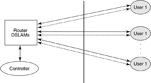
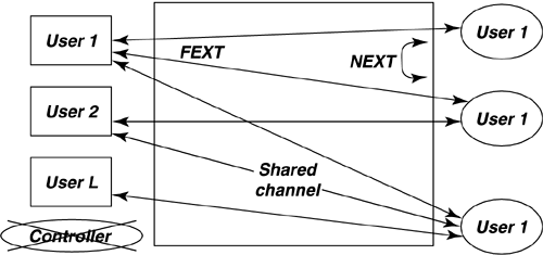
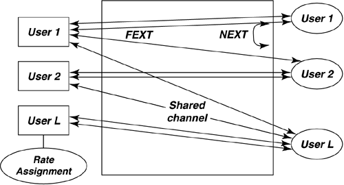
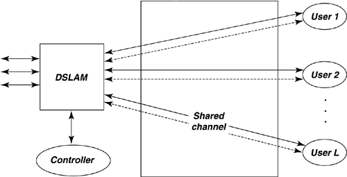
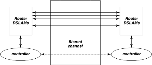
| Dynamic spectrum management embodies multiple- user communication concepts. All the situations introduced in Section 11.1 contemplate the potential of multiple DSL users who occupy lines in the same binder. These lines may interfere with one another. The resultant crosstalk often is the limiting factor in DSL deployments, determining speeds, ranges, and, indirectly, costs of installation. The possibility of coordinated control of some or all lines for global benefit of all customers is a goal of DSM. This chapter primarily addresses frequency domain dynamic spectrum management. It is also possible to coordinate the transmission of many lines in the time domain, for burst-mode systems. Such packet level network use is an additional improvement that can occur independently with proper DSM and system design. DSM's consequent shared use of the communications facility falls into a mathematical science that is called "multiuser information theory" (see [3],[4]). Thus, although DSL initially appears to be a single user on each line, crosstalk effects actually create a shared or matrix channel. The best transmission strategy for a multiuser situation is sometimes not the best transmission strategy for an isolated channel. Figure 11.6 illustrates this multiuser channel for the DSL case. Each of the users on the right can correspond to a customer premises in DSL where one or more phone lines enter the premises for the access to a particular user. On the left, typically the users are in a common building or facility, like a CO or a remote/line terminal. Any coordination of users' signals may thus be easier on the left or service provider side. In the most general case, the lines may have no means of coordination whatsoever. Static spectrum management standards such as T1.417 [5] are an early attempt to address the uncoordinated situation. DSM standards contemplate the judicious use of the self-optimizing spectra of various DSL modems, particularly ADSL and DMT VDSL, but are not limited to those most heavily deployed DSLs. DSM additionally contemplates optional use of the controller, also shown in Figure 11.6. This controller may combine the processes of information acquisition, optimization, and/or control. The controller may specify only the data rates of the various downstream and upstream transmissions or may specify more complete signal-generating information such as spectra or even vectored transmissions. Clearly in the upstream direction, the maximum possible specification is the spectra of physically separated modems. The upstream spectra would be controlled via commands sent over the transmission link, and are indicated by the dashed lines in Figure 11.6. Downstream signals may have their signals cogenerated. Clearly channel information may also flow along these dotted lines to the controller to assist its determination of best spectrum policy for the binder group illustrated by the vertical dashed line. Problems can be isolated and/or averted by avoiding difficult crosstalk coupling paths, thus simplifying deployment and reducing costs of service. Also, a well-designed controller/DSLAM configuration might well lead to lower complexities and power consumption on the DSL lines (e.g., better performance could be exploited by sending less power, and thus reducing costs of critical line-driver circuits. Additionally, signal processing may be shared among the lines, further reducing complexity and power for the DSLAM. Figure 11.6. Basic multiuser DSL configuration. This section develops the basic terminology for the use of multiuser information theory concepts in DSL in Section 11.2.1 on multiuser coordination levels and Section 11.2.2 on the matrix channel. A theory known as generalized decision feedback equalization (GDFE) is introduced in Section 11.2.3 and can be used to develop nearly every concept and structure in multiuser information theory's handling of crosstalking channels. Sections 11.3 “11.5 will follow with specific implementations of various mutiuser structures with increasing levels of permitted coordination from none to substantial. 11.2.1 Multiuser Channels and Rate RegionsMultiuser channels as in Figure 11.6 are necessarily characterized by several variables that this subsection summarizes.
Some of the types and levels of coordination are not mutually exclusive. For instance, not all the lines may report or allow control of spectra or signals. It is possible to have a few older DSL lines that are uncooperative and used fixed spectrum masks, whereas others may report their channel characteristics, and still yet others may have the additional ability to allow control of their spectra. There may be groups of lines that allow vectoring, but may or may not be able to be coordinated with other lines or groups of lines. Cogent DSL evolution may need to encompass DSM strategies and solutions that at least always do as well as a system without the additional incremental allowance of cooperation. 11.2.2 The Matrix ChannelChannel Transfer FunctionAny of the L x L shared channels in Figures 11.8 to 11.11 can be represented by a matrix equation where H ( f ) is an L x L matrix of channel transfer functions, X ( f ) is an L x 1 vector of channel inputs, and Y ( f ) is a L x 1 vector of channel outputs. This relation generalizes in a simple manner the traditional scalar relation that is used in point-to-point DSL (often with any coupled crosstalk signal from another line instead modeled simply as a component of noise added to the channel output). The matrix channel transfer function is where H km ( f ) is the channel transfer function from line m to line k . [2] A continuous transform is indicated here to avoid the difficulty associated with possibly asynchronous clocking of DSL circuits. Many of the transfer functions between lines may be zero or practically negligible, but there are a few dominant crosstalkers into each line (and which is dominant may depend strongly on frequency). A method for determining H ( f ) appears in [6].
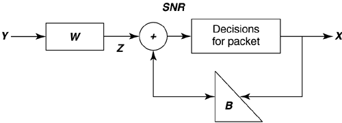
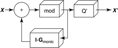
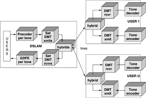
There are of course two transfer functions for downstream and upstream; however, basic reciprocity in electromagnetic theory forces these two functions to essentially be the same mathematically although real cables can exhibit deviation from reciprocity. For line signals traveling in opposite directions, NEXT coupling is also potentially of interest even for frequency-division multiplexed systems (as in DSL). In this case, the NEXT insertion-loss transfer function from line m in one direction to line k at the same side of the binder is G km ( f ). The L x L matrix is G ( f ), and G kk ( f ) measures echo on line k . The above does not address the additional complexities of repeatered lines where reciprocity of course does not apply, and each line between repeaters should be individually considered . Also of interest and easier to compute sometimes are the channel magnitude profiles The virtual binder group is that set of couplings or pairs of lines M k , such that the maximum coupling from m into k exceeds a threshold The channel is often replaced by a vector packet time “domain matrix model that is derived by inverse transforming H ( f ) to the time domain to get h ( t ) and then sampling at h ( t ) some desirable sampling rate 1/ T' , and rectangularly win-dowing to some convenient sufficiently long packet interval in time, call it NT' to get h = h (t) t =0:( N -1) T' . Then a packet time “domain vector equivalent of the channel can be formed , and with a slight reuse and abuse of notation, a packet channel model can be formed from the samples in the matrix h by reordering corresponding to inputs, outputs, and convolution (perhaps with guard intervals to make sure there is no overlap between packets) to get Y = HX. This latter model is actually the one used most heavily in signal processing and receiver design. The sampling rate needs to be chosen sufficiently high so that all signals of interest are represented. Further, the inputs of the different DSL channels represented in X may be at different symbol rates than the sampling rate. Polyphase interpolation of the input-channel convolution to the correct sampling rate may be necessary. For more on such models, see [7]. Clearly, the fundamental model is easy. The interpolation may take some effort to understand, but that is not of consequence to basic principles being developed in this chapter although it will eventually be very important to a designer of detailed receiving equipment. NoisesNoise sometimes includes crosstalk, and always did in earlier SM studies. Any crosstalking signal not in M k is still a contributor to noise. Other noise sources are the inevitable thermal-line, resistive-termination, and radio-frequency noises. Impulse noise is also of great concern, and was addressed in Chapter 3. Noise will be identified by a power spectrum N ( f ). This residual noise has been modeled in all types of spectrum management as Gaussian. Dynamic spectrum management in this chapter will presume that the DSL modems autonomously measure this spectrum and report it, rather than assume it to be some fixed model. The measurement procedure and accuracy for the noise power spectrum needs definition and specification. For example procedures, see [8] and [9]. Source InformationThe power level transmitted by any DSL line is known to that line only and cannot be measured absolutely on another line. There is always an ambiguity without specific knowledge of the transmit power spectrum of whether a signal measured at significant levels has absolute scaling determined by transmit power or by coupling between lines. Fortunately, this does not matter unless power levels are to be mutually controlled across many lines. In this case, the power spectral density of the transmitter S m ( f ) can be reported by a modem. Today, g.dmt.bis (g.992.3) modems already provide all the source, noise, and H km ( f ) information necessary. Clocking information is important; fortunately, signal processing methods exist at any point in a system to determine appropriate clock offset between any two signals in a virtual binder group [8], [10]. A Packet-Channel ModelThe packet-channel model appears in Figure 11.12 and is applicable to all levels of coordination. The additive noise includes any crosstalk not already in X. The input vector corresponds to U users, but may actually be LN dimensional where N again is the packet length for the set of users (which may be a maximum over the set). Basically N is an observation interval in the most general case over which the receiver will elect to sample and store successive outputs from each of the DSL lines. The matrix thus can be very large if N is sufficiently large to model the inherent ISI in each of the DSL channels. Any consequent matrix operations on the received vector Y that occur even in suboptimal receivers would have enormous complexity. Fortunately a simplification exists for DMT, which is the most widely used modulation format for DSL. When the cyclic prefix is used (and especially when the digital duplexing of Chapter 7 allows desirable alignment of DMT transmit symbols on all coordinated lines), each of the individual tones in a DMT system has an independent model of the type in Figure 11.12. The size of the matrix is then just the size of the virtual binder group at each frequency, which is typically a 2 x 2 matrix, or sometimes a 3 x 3 matrix and in no case more than a 4 x 4 matrix. Matrix operations on each tone can then be independently executed with very small matrices, or essentially scalar complexity. Multiuser systems with nonfrequency-domain processing (i.e., PAM, QAM, CAD) have inherently much larger matrices and consequently an enormously higher complexity. Time-domain approaches have received less attention because they are suboptimal and complicated with multiple users and intersymbol interference. Furthermore, almost the entire wide literature on multiuser spectrum allocation today is predicated on the use of frequency-domain modulation methods. Ordering of the tones for simplest processing is important and presently remains an area of proprietary technology. Figure 11.12. Packet modeling of matrix channel. In any case, whether for each tone or for a large packet, the channel model mathematically is where the dimensions of Y and X depend on the number of lines L and on the packet size N and thus H could be as large as an LN x LN matrix. For DMT systems, this is never at any frequency more than a 4 x 4 matrix because the number of significant crosstalkers at any one frequency rarely exceeds 4. 11.2.3 GDFE TheoryGeneralized decision feedback equalization (GDFE) is described in several other references [11 “14] and resembles the simple DFE often known to transmission theorists for removing intersymbol interference from a single-channel transmission. In its most general form, the GDFE structure views interuser interference and intersymbol interference essentially on the same level and works to eliminate all crosstalk or intersymbol interference from a transmitted signal. Even DMT systems are a special case of the GDFE theory ”indeed a very special case when the structure has best performance guaranteed . The equivalent of the DMT single-user channel partitioning [1] across the user dimensions is known as vectoring and is determined by singular value decomposition of the channel matrix H . Vectoring leads to best multiuser performance when it can be implemented. The GDFE applies to any channel of the form Y = HX + N and hence to the packet DSL model in Figure 11.12. The GDFE attempts to estimate the vector of all the users' inputs X by the structure shown in Figure 11.13. A feedforward matrix W causes the matrix-filtered channel output Z = WY to appear triangular in structure. The triangular matrix created is such that it is monic, that is, it has ones on all diagonal elements, B. The result is Figure 11.13. Generalized decision feedback equalization. where E is an error matrix that is essentially "white" noise, that is, R ee = E [EE * ] is diagonal. The first output of the packet Z is free of crosstalk and can be estimated by a simple slicer or memoryless decoder. This first decision, presumed correct, can then be used to subtract the crosstalk or ISI from the second packet output in Z. Then simple decoding is applied to that second output, and the process proceeds through the entire packet, each time subtracting crosstalk or ISI and then making a simple decision. A GDFE structure of one sort or another will appear in all multiuser situations of interest in DSL. This section introduces the general concept, and then later sections use the GDFE later as a tool for the solution of each particular level of allowed coordination in DSL. The GDFE decision process is prone to errors in multiuser transmission and thus the simple slicer and feedback subtraction may be replaced by an iterative decoder as described in the appendix at the end of this chapter. With the correct choice of W and B , it is possible to show that the GDFE- processed system is equivalent to an AWGN noise channel that has the maximum possible SNR that theory admits for the multiuser channel. Good codes (like turbo codes) applied outside the system will drive the performance to the highest possible sum of user rates on the channel. A GDFE structure exists for all possible input choices, and clearly some inputs will be better than others, so an additional step is to optimize the input. Best inputs often separate the spectra of users, as well as determine several independent best bands for each user, in which case the GDFE often decomposes into a set of N independent structures of the type in Figure 11.13. In no case is this more evident than when all lines use the digitally duplexed DMT system that synchronizes frames of transmission as described in Chapter 7. In this case, there is an independent GDFE for each tone, and the only interference left is crosstalk on the same tone between different DSL lines. This later residual independent-per-tone crosstalk can be handled easily and well in several ways, as will become evident. With correct decisions, the GDFE essentially creates NL (the dimensionality of X ) parallel AWGNs, one for each tone of each user. Many of these parallel channels may have zeroed inputs. The rest of the AWGNs pass energy and may be loaded with a number of bits proportional to the log of the gap-reduced-SNR (see [1]) on that particular channel. For any given choice of input spectra on all the users, the GDFE will have a product of such SNRs that is maximum (and equal to 2 2I (X; Y ) where I ( X;Y ) is the mutual information for the vectored channel), and thus the data rate for that choice of input spectra is maximum. The best overall SNR requires input optimization and maximizes the best sum of rates of all the users, which is C = max I ( X;Y ). The best sum is only one possible solution for the multiuser situation, and the rate region is actually often more of interest, of which the rate-sum maximum will just be one of the boundary points. In formulating the input X , this higher level development ignores the differences in clocks or sampling rates that may exist between different DSLs, especially different types of xDSLs. Nonetheless, these offsets can always be determined by signal processing and used to interpolate and construct an appropriate matrix H for each packet of transmitted signals from all the users. This chapter pursues this interpolation in Section 11.5. DSL's Noteworthy Simplification ”Ginis's QR GDFE for Square Channels A special case of the GDFE occurs when a zero-forcing criteria is imposed on the nominally involved computation of the W and B matrices and the channel is square (that is, coordination occurs at signal level). This ZF-GDFE is found by setting the residual non-FEXT crosstalk noise to zero. Nominally, this is a horrible thing to do in GDFE theory and can result in catastrophic misconclusions; however, for DSL, FEXT matrices H the off-diagonal terms are at least 100 times smaller than the on-diagonal terms in practice when DMT is used to simplify the problem into a set of independent GDFEs for each tone. This is essentially equivalent to noting that if all DSL modems on one side of the link, that is, the DSLAM side, are colocated , then it must be true at each receiver that the coupling of FEXT over the common length between transmitter m and receiver m must necessarily have less gain from any other transmitter i The ZF-GDFE is always essentially equivalent in performance to the GDFE under these situations, and furthermore the ZF-GDFE can be much more easily specified as Ginis notes from the "QR" decomposition of the matrix H: where Q is an orthogonal matrix satisfying QQ ' = I = Q ' Q and G is a triangular matrix. The factorization QG exists for any square matrix (even singular ones), and is not necessarily unique. It is convenient to write G in terms of a monic matrix G = DG monic where D is a diagonal matrix but is unique if all users are present (nonsingular) and the order of the users is specified. In this case, the GDFE becomes and The signal-to-noise ratio for each user on each tone with correct decisions becomes where D m is the m th diagonal (user) element of D, P x ( m , n ) is the power of the m th user on the n th DMT tone, and s 2 is the background AWGN (e.g., “140 dBm/Hz). The product of the SNRs is the highest possible for any receiver and achieves the best possible data rate (with good codes). Water-filling optimization can be applied to all the user's tones as a set to maximize the sum of the data rates that can be achieved with such a channel. Clearly, perhaps by design, it is possible for some of the diagonal elements to be zero (corresponding to perhaps intentional silencing of a particular user on a particular frequency). These users on any tone should be deleted from further consideration, which simply means that the corresponding row of Q ' in the product Q ' D + is deleted. Note the use of the + sign in the exponent to indicate "pseudoinverse," which means 1/0 is defined to be 0 in this case. In practice, presumably this user's zero contribution would be known in advance, and the corresponding entry eliminated in advance from the H matrix (which has the same effect as using the psuedoinverse). Furthermore, with the use of such a structure, the coordination need only be on the receiver side. H is whatever it is for the possible use of transmitters that cannot coordinate their signals. Thus the QR-DFE applies directly to upstream DSL transmission where the DSLAM can possibly coordinate all the received signals (especially in situations like a remote terminal where all signals emanating from the user terminate on a common DSLAM). Downstream, the channel matrix is factored in a left-handed QR factorization H = DG monic Q (not the same Q, G and D as above), and the Ginis precoded structure of Figure 11.14 applies instead. Each user channel needs to scale itself prior to a modulo (wraparound) device that is similar to the Tomlinson precoder of [1]. Figure 11.14. Ginis precoder ”the channel output is HX' = DX where D is diagonal, so simply scaling by D -1 can be executed separately at each independent receiver. For some levels of lesser coordination between lines, the H matrix is nonsquare and necessarily then has zero singular values. QR factorization is still possible but is nonunique , and some of the diagonal elements of the resulting R matrix will be thus be zero. Unfortunately, the GDFE will estimate only certain nonsingular "pass-space" dimensions of the input that correspond to linear combinations of the multiple users in general. Thus, simple slicing decisions become somewhat ludicrous unless the inputs have been carefully chosen to lie in this space with simply implemented decisions. Thus instead, a maximum likelihood decision on the signal Z = WY = WHX + WN , which means either trying all possible vector values for X or somehow approximating this (as in the appendix) with iterative decoding. Thus, the feedback section in Figure 11.13 is replaced by a ML decoder, or an approximation to it like an interative decoder. More generally , the MMSE GDFE settings can be found in any case via the following notational simplifications . The GDFE error vector is with mean-square matrix R EE = E [EE * ] thus determined as for any triangular monic matrix value of B and optimum value of W = BR XX H * ( HR XX H * + s 2 I ) -1 The minimizing B can be determined by generalized Cholesky factorization [13] “[14] of the inverse of the internal matrix in the equation above for R EE , and regular Cholesky factorization if this internal matrix is nonsingular. In either case, then where S is diagonal, G is monic lower triangular (same structure as B), and the optimum feedback section is B = G . A zeroed entry on the diagonal of S is indicative of an input that cannot be estimated because it has some component along a direction that the channel does not pass (which can occur often in multiuser situations). The MMSE is infinite, and the system fails in this case to estimate all input symbol values. However, individual components may not have infinite MMSEs themselves and are estimated by the GDFE with the error corresponding to the diagonal element of the matrix R EE corresponding to that component. Simply stated, the input components that cannot be estimated cannot help in any of the other symbol estimates, and their respective decision outputs should just be zero as far as the feedback to other components is concerned . The corresponding elements of B should also be zeroed in the MMSE equation. Generalized Cholesky factorization proceeds according to a Gram-Schmidt decomposition of the matrix in the above equation (see [13, 14]) and essentially leaves zeroed values of the diagonal matrix S when prediction errors associated with linear combinations of previously processed elements are zero. The corresponding values of a row or column of the triangular matrices are set to force the zero prediction (and the choices for G become nonunique). An adaptive implementation would need to know those input symbols that cannot be estimated because the channel does not pass them. The implementation should delete them to avoid numerical "blow-up" of the GDFE. This effect will dominate multiuser situations while it only occurs with ludicrous design choices in single-user DFEs. A better development that suggests aversion of transmission on singular modes of the multidimensional channel when possible appears in [11 “14] but is beyond the mathematical scope of this chapter. Fortunately, the case with DMT and independent GDFEs per tone does not exhibit any of these problems and can also use Ginis's simplifications. Figure 11.15. One-sided vectoring for DMT VDSL. |
| Top |
EAN: 2147483647
Pages: 154
