9.4 The Primary DSL Signal Spectra
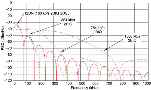
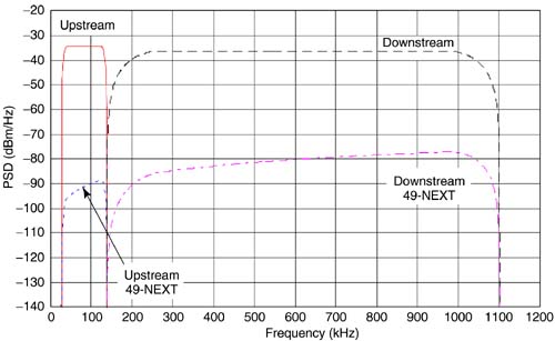
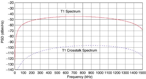
9.4 The "Primary" DSL Signal SpectraThis section describes power spectral densities of different DSL transmit signals that are deployed in the network. The label "primary" means that the DSL systems described here were the early generation to be deployed; hence they form the basis for definition of spectral compatibility. The standards based DSL include ISDN (integrated services digital network), HDSL (high-rate digital subscriber line), and DMT-based ADSL (asymmetric digital subscriber line). Other DSLs signals include 2B1Q based SDSL (symmetric digital subscriber line), CAP-based MSDSL ( multirate symmetric digital subscriber line), and CAP-based RADSL (rate adaptive digital subscriber line) per Committee T1 TR-059. The signals targeting symmetric transmission applications include ISDN, HDSL, SDSL, and MSDSL, and those targeting data access applications are ADSL and RADSL. Following are descriptions of the signal power spectral densities for each of the above signals. 9.4.1 ISDNISDN basic rate provides symmetrical transport of 160 kb/s on the subscriber line. The line code is 2B1Q, and the corresponding transmit signal power spectral density is expressed as [3] where f o = 80 kHz, V p = 2.5 Volts and R = 135 Ohms. The transmit power of ISDN is 13.5 dBm. In Figure 9.5, the solid line plots the power spectral density of the ISDN transmit signal. Included in the plot is the effect of a high-pass filter with a cutoff frequency at 2 kHz, which models the transformer coupling of the signal onto the line. Figure 9.5. ISDN transmit signal and 49-NEXT spectra. Also shown in the figure ( dotted plot) is the PSD of 49 near-end crosstalk disturbers from ISDN. As defined in references [2, 3, 5, 6, and 12], the noise floor of the system ( modeled at the receiver input) is - 140 dBm/Hz. Both the upstream and downstream signals occupy the same frequency band , so an echo canceler is used to separate the two directions of transmission on the subscriber line. In such a system, ISDN is subject to self-near-end crosstalk (SNEXT). The deployment objective for ISDN is to operate on nonloaded loops that range up to 18 kft in the presence of SNEXT. These include all loops that meet RRD rules. 9.4.2 HDSLIn North America, HDSL is a service that provides the transport of T1 (1.544 Mb/s) signals between the CO and the CP. This service is deployed using two subscriber lines (e.g., four wires), where the bit rate is 784 kb/s on each wire pair and half of the T1 payload is carried on each pair. The line code is 2B1Q, and the corresponding transmit signal power spectral density is expressed as where f o = 392 kHz, V p = 2.7 Volts and R = 135 Ohms [5, 6, 13]. The transmit power of the HDSL signal is 13.5 dBm. In Figure 9.6, the solid line plots the power spectral density of the HDSL signal. Included in this plot (but not shown in the preceding equation) is a high-pass filter with a 2 kHz cutoff frequency to model the effects of transformer coupling. The dotted plot is the PSD of 49 near-end crosstalk disturbers from HDSL. Figure 9.6. HDSL transmit signal and 49-NEXT spectra. Both the upstream and downstream signals occupy the same frequency band, so an echo canceler is used to separate the two directions of transmission on the subscriber line. In such a system, HDSL is subject to SNEXT. The deployment objectives for HDSL are operation on loops that meet CSA requirements while operating in the presence of SNEXT. 9.4.3 Symmetric DSL TechnologiesSDSL technologies define the transport of symmetric DSL services on a single twisted wire pair. SDSL solutions deployed are echo cancellation based and are implemented using CAP and 2B1Q technologies. To distinguish between the two technologies, we refer to the 2B1Q solutions as SDSL and to the CAP-based solutions as MSDSL. The MSDSL bit rates considered here are 160 kb/s, 272 kb/s, 400 kb/s, 784 kb/s, and 1560 kb/s. Each of the CAP-based systems assumes a two-dimensional eight-state trellis code to provide additional immunity to crosstalk. Figure 9.7 shows the spectral plots of the MSDSL spectra. The bandwidth of each spectrum is directly proportional to the bit rate, so the 160 kb/s signal has the narrowest bandwidth and the 1560 kb/s signal has the widest bandwidth. The line codes for each system are as follows : 160 kb/s uses coded 8-CAP (2 data bits per symbol), 272 kb/s and 400 kb/s each use coded 16-CAP (3 data bits per symbol), and 784 kb/s and 1560 kb/s each use coded 64-CAP (5 data bits per symbol). The spectral shaping of each transmit signal is square-root raised cosine with a roll-off factor of 15 percent. For each bit rate, the spectrum is scaled and shaped for a transmit power of 13.5 dBm. Figure 9.7. MSDSL transmit signal spectra. Figure 9.8 shows the SDSL power spectral density plots for four data rates: 160 kb/s, 384 kb/s, 784 kb/s, and 1560 kb/s. Each system uses NRZ (nonreturn to zero) shaping followed by an N-th order Butterworth filter. The 160 kb/s spectrum is the same as that defined for ISDN in T1.601, which defines a second-order Butterworth filter for out of band energy attenuation. The remaining signals use a fourth-order Butterworth filter for out of band energy attenuation. The first null in each spectrum defines the signal bandwidth. Figure 9.8. 2B1Q-based SDSL transmit signal spectra. If we compare the PSDs of Figure 9.7 with those of Figure 9.8, the bandwidths of the multilevel CAP systems are narrower than those of the four level (2B1Q) systems for the same bit rate. Also, the spectral efficiency of the raised cosine shaping has significantly less energy in the high frequency out-of-band region that the NRZ shaping of the 2B1Q signals. From these figures, it is clear that the spectra with the more efficient spectral shaping will provide less interference into other systems at the higher frequencies. For the same transmit power, the performance of both the CAP and 2B1Q systems are dominated by SNEXT. If the 50-pair cable is deployed with signals having different bandwidths, then consideration must be given to the effect that these different bandwidths have in producing NEXT onto other services. Recall that the NEXT coupling is greater at higher frequencies than at lower frequencies. As described earlier, the NEXT coupling increases at 15 dB/ decade with increasing frequency. 9.4.4 ADSL and RADSLFigure 9.9 shows transmit and near-end crosstalk spectral plots of the upstream and downstream ADSL channels. The same upstream and downstream bands are used for both ADSL [T1.413, G.dmt, and G.lite) and single-carrier RADSL [TR-059]. In general, ADSL and single-carrier RADSL are variable bit rate systems and the actual bandwidths of the upstream and downstream channels may vary depending on the bit rate and noise environment. Figure 9.9. ADSL and RADSL FDM signal spectra. The plots shown in Figure 9.9 are idealized PSDs displaying the maximum possible bandwidth of the upstream and downstream channels. Not shown in the figure are the out-of-band energy levels.Usually the PSD levels represent the RMS values. However, for ADSL the PSD levels shown in the figure are peak values as opposed to RMS values [12] to allow for varying gains at different carrier frequencies. No guard band is specified between the upstream and downstream channel; details of the DMT PSD masks are given in the ADSL standard [T1.413, G.dmt, and G.lite]. The spectra shown in Figure 9.9 use frequency division multiplexing (FDM) to separate the upstream and downstream channel. If the cable has only FDM-based ADSL systems deployed, there is no SNEXT; system performance would be limited by SFEXT. T1.413 and G.dmt also defines an echo- canceled version of ADSL, where the downstream channel completely overlaps the upstream channel. In this case, NEXT will be injected between the upstream and downstream channel. The channel most impacted is the upstream channel, where the NEXT from the downstream channel completely covers the upstream band. RADSL systems per TR-059 have only been deployed using FDM for separation of the upstream and downstream channels; hence there is no NEXT generated between the upstream and downstream channels. The complete definition of the RADSL PSD masks is given in [9]. 9.4.5 T1 AMIThe PSD of the T1 line signal is assumed to be a 50 percent duty-cycle random alternate mark inversion (AMI) code at 1.544 Mb/s. The single-sided PSD is represented by the following expression: Figure 9.10. T1 AMI signal and crosstalk spectra. Unlike most DSLs, T1 carrier does not scramble the transmitted bits. As a result, the actual PSD at any time is highly dependent on the payload bit pattern. |

 where
where  ,
, 
| Top |
EAN: 2147483647
Pages: 154