7.4 Multiple-QAM Approaches and Standards
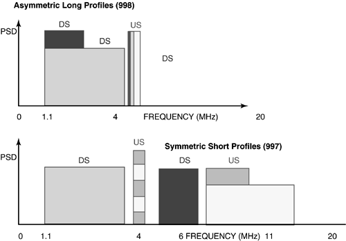
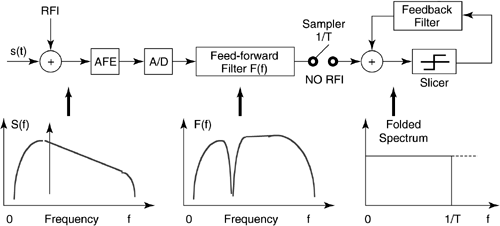
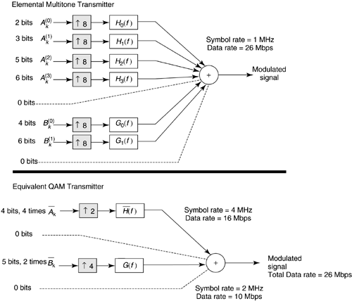
| The VDSL system specified in [16] uses either CAP or QAM as a modulation scheme [6], and analog frequency division duplexing (FDD) to separate the upstream and downstream channels. There are two carriers or equivalently center frequencies, both with 20 percent excess bandwidth raised cosine transmission in each direction, following frequency plans 997 (Europe) or 998 (North America). The symbol rate of each of the signals is any integer multiple of 67.5 kHz, and the carrier/center frequencies can also be programmed as any integer multiple of 33.75 kHz. This allows for the receiver for each signal to estimate signal quality and request an appropriate center frequency and symbol rate, as well as corresponding signal constellation, which can be any integer QAM constellation from four points to 256 points as described in detail in [16]. Radio frequency emission control occurs through programmable notch filters in the transmitter, for which a decision feedback equalizer in the receiver can partially compensate. With overhead included, data rates are certain integer multiples (not all) of 64 kbps up to 51.84 Mbps downstream and 25.92 Mbps upstream. SCM advocates sometimes cite "blind operation" ”that is, no training, as an advantage, but of course one data rate must be fixed for all systems for true blind operation. 7.4.1 Profiling in SCM VDSLTo accommodate short (< 1 kft), medium (1000 “3000 feet) and long (> 3000 feet) transmission at both asymmetric and symmetric rates, SCM VDSL can transmit up to four QAM signals, two in each direction. For long loops , only one carrier downstream and one carrier upstream (just above the downstream band ) are permitted. For medium range, a second downstream carrier is permitted in addition to the two carriers of long loops, while the short loops can use all four carriers. It was basically this four-max carrier restriction of SCM that forced the number of bands in the 997 and 998 frequency plans. Using four bands is otherwise very suboptimal and unnecessary as mentioned earlier. Figure 7.22 depicts the concepts of the profiles that are created by altering the center frequencies and symbol rates chosen . Notches at radio bands must be inserted to ensure emissions meet radio requirements; however, there are not a sufficient number of carriers to simply achieve this notching by reversing direction, although the 998 spectrum plan does leave one radio band as a reversal point near 4 MHz between upstream and downstream transmission. Figure 7.22. Basic concept of profiling in SCM VDSL. As Figure 7.22 illustrates, larger symbol rates will likely be accompanied by larger center/carrier frequencies. Decision feedback equalization (DFE) is presumed in the receiver and no Tomlinson precoding is used, even though FEC is used. The FEC in [16] and interleaving are basically identical to those used in the DMT standard. The DFE is described in the next subsection. 7.4.2 Operation of the DFEThe way a DFE handles RF interference (RFI) and notching is briefly discussed with reference to Figure 7.23. Figure 7.23. Principle of operation of the DFE in the presence of RFI. The analog front end (AFE) of any VDSL system needs to do some analog processing to reduce very strong RFI to an acceptable level and avoid overloading of the receiver's A/D and other input circuitry . This issue is not discussed any further here. The feed-forward filter of the DFE creates a notch around the frequency at which the RF interferer is located, so that very little RFI is present at the output of this adaptive filter. The energy that is removed from the received signal by this notch is then restored by the feedback filter in such a way that the folded spectrum at the input of the slicer is flat. Actually, this is often claimed to be optimum performance by SCM advocates, but it is not. Optimum performance can only occur when the transmit band is silenced, and more carriers are used to have a QAM signal on each side of the notch [25]. DFEs with multiple or single deep notches can require high-precision implementation and must execute at the symbol rate, leading to billions of operations per second being required at VDSL speeds. Most QAM designers reduce the number of taps from the levels needed for excellent performance because of this complexity problem. Instead, designers hope that the difficult notching is not required often and that the small number of taps in the equalizer is sufficient. In a way, SCM VDSL designers reduced system complexity in early chips by sacrificing performance on difficult channels and hoping that the low-complexity chips would be consequently attractive. QAM is well suited with the DFE on channels that have continuous transmission bands and mediocre distortion, where it can eliminate generation of multiple carriers. However, as the channel distortion grows, the complexity of the DFE quickly overtakes the complexity of the multiple carrier generation, and QAM cannot handle channels with the severest distortion of VDSL well. SCM designers hope that an early low-cost solution can be replaced by increasing complex QAM components of the future that gradually address an increasing number of severe distortion situations in VDSL. 7.4.3 FMTAn informative annex of [17] contains a filtered multitone (FMT) system [26], which is actually based on the principle of profiling and QAM transmission in [16]. This approach of specifying 8 to 256 carriers according to profiling that is enhanced with respect to [16] had been acceptable to some DMT and SCM advocates as a compromise to the grand debate. However, elements of both sides found the proposal either too complex (DMT advocates) or resembling DMT too much (SCM advocates), and so the proposal was provided for information only in the DMT draft standard [17], although it more appropriately fits the SCM model and so is listed in this section here. For more details, the reader can refer to the annex of [17]. Rather here we pursue a general theory of equivalence in transmission in the hope to add to what is in [17] in terms of understanding. Reference [26] describes a transmission method that is intermediate to multitone and QAM/CAP transmission methods in that both types of signals can be constructed using elements in that contribution. This section contains an example that illustrates the construction of either type of signal. The following section on equivalence simplifies the basics of so-called "equivalence theory" [27], which outlines the conditions for equivalent performance of QAM/CAP methods and multichannel (or DMT) transmission methods. The areas of bandwidth optimization and interpolation/decimation are also addressed in the section below on equivalence. The section on paradox provides a second example called the "Bandwidth Optimization Paradox" in equivalence theory that illustrates the effect of incorrectly satisfying the equivalence conditions. This situation happens often in the VDSL transmission area, almost always when RF ingress/egress constraints are present and also commonly when bridged-taps or frequency-selective large-amplitude crosstalk is present. EquivalenceReferences [27] and [28] are sometimes cited as noting performance equivalence of various types of modulation methods, including, but not limited to, DMT and CAP/QAM/SCM. The methods in [26] are generally within the main consideration in [27] with the finite-delay packet realizations considered in [28]. The conditions for equivalence are sometimes also not well understood nor well translated. To simplify understanding of the conditions, this section illustrates equivalent transmitters and receivers for infinite-length filters. After viewing these examples, this section progresses to stating the general equivalence conditions, but in simple non-mathematical terms, along with a "CDEF" (authors of reference [27] in alphabetical order) formula that allows computation of system performance. Transmit EquivalenceFigure 7.24 illustrates equivalent transmitters based on a bank [26] of 8 equal bandwidth filters for modulation. Channel characteristics are such in this system that the optimum bandwidth use (which can be found through a procedure known as " water-filling '' [27]) uses only 6 of the filter bands. Four of the used bands (set A) are adjacent, and the other 2 (set B) are also adjacent. Sets A and B, however, are separated by an unused band. [10]
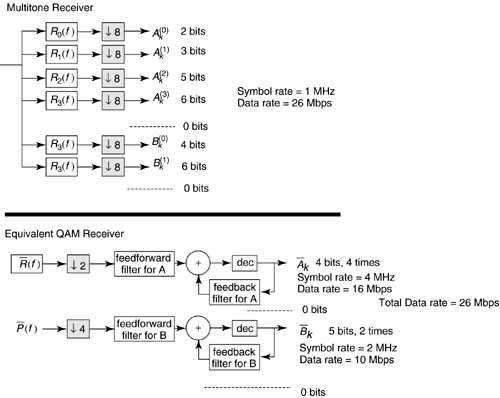
Figure 7.24. Transmitter equivalence example. The bands in Set A can carry 2, 3, 5, and 6 bits, respectively, corresponding to increasing signal-to-noise ratios in the corresponding channel, while the two bands in Set B can carry 4 and 6 bits, respectively. The unused bands carry 0 bits. The average number of bits per band in Set A is 4, and the average number in Set B is 5. If the symbol rate for the system is 1 MHz, then the data rate is 26 = (2 + 3 + 5 + 6 + 4 + 6) bits transmitted 1 million times per second for a total data rate of 26 Mbps. For equivalent performance, a QAM system with two bands of different width may be used instead as also shown in Figure 7.24. The first A band has a symbol rate of 4 MHz and carries 4 bits on all symbols for a data rate of 16 Mbps. The B band carries 10 Mbps at a symbol rate of 2 MHz with 5 bits on all symbols. The total data rate is also 26 Mbps. With the correct choice of receiver for each system (see Figure 7.25), the performance of the two systems in Figures 7.24 and 7.25 is identical. Figure 7.25. Receiver equivalence example. Note that the carrier frequencies and symbol rates for the CAP/QAM system have been chosen so that the used bands exactly correspond to those in the multitone transmission system. Further, the average number of bits in any set of multitone bands must equal the fixed number of bits used in the corresponding QAM/CAP band. The example could be extended to any number of sets of bands in a straightforward manner following the same rules of using the same bandwidth and average bits/band for all separate bands. In VDSL, seven or more disjoint bands are common because there are many gaps in used spectrum caused by RF ingress/egress constraints (there are five amateur radio bands alone that overlap VDSL), bridged-tap notches, and frequency selective large crosstalk (e.g., a home LAN signal). Receiver EquivalenceFigure 7.25 illustrates the corresponding receivers for the transmitters of Figure 7.24. The multitone system chooses an appropriate set of matched filters and directly decodes the outputs of each band. No equalizer is necessary within any band because each band is free of intersymbol and intraband interference. The complexity of modulation is contained within the transmit filters and corresponding receiver filters entirely: DMT systems use a cyclic prefix and FFT to implement the filters, but there are other approaches to filter implementation as in [26]. The QAM/CAP system uses a decision feedback equalizer (DFE) for each band. The DMT and QAM systems will be equivalent if the transmit spectra are the same as in Figure 7.26. Reference [27] shows that the MMSE-DFE converts each band into the equivalent of an intersymbol-interference-free additive white Gaussian noise channel and the signal-to-noise ratio of this channel is computed according to Figure 7.26. Example of the common paradox. where C, the capacity in bits per Hz for the particular band and DFE under study, is a function of the channel. This result presumes an infinite number of DFE taps and may be difficult to approach in practical implementation. An equivalent SNR for any correctly designed multitone system is well known to follow the same expression. The formula does not mean that either system operates at capacity unless extremely powerful codes with no extra margin are used. However, as long as the same code of the same power is used in both systems, then the suboptimum performance is the same in each band for both the multitone and the infinite-DFE-equalized QAM system. For the QAM system in Figures 7.24 and 7.25, let us assume that uncoded QAM is used on both the 4-bit and the 5-bit subchannels and the performance is measured to be at probability of symbol error approximately 10 -6 . The capacities are approximately 3 bits per Hz higher than what uncoded QAM transmission can achieve and so are equal to 4 + 3 = 7 and 5 + 3 = 8 bits/Hz, respectively. Thus the DFE and MT SNRs are for band A, and for band B. An overall SNR can be computed as in [28], but is not necessary for the present discussion. Conditions for EquivalenceSimply stated and paraphrased from [27] and [28], the QAM/CAP systems and multitone system have the same performance when:
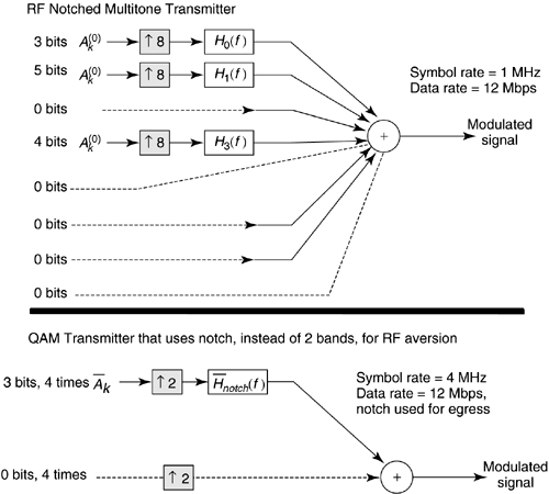
When these conditions are met, the CDEF result can be used to compute the SNR level achievable by either multitone or infinite-DFE-equalized QAM(S) in each band as long as the capacity in bits/Hz for each band is known (the capacity is fundamental to each channel and can be computed through well-known water filling methods that are also summarized in [27] and the references therein). It should be noted that a single used band replacing several separated bands does not perform as well regardless what receiver structure is used. There must be a separate modulated signal and separate DFE for each separate band. Intuitively, this means that when the best spectrum has gaps that a transmit band-reject, or equivalently a "notch" filter is not sufficient to reach best performance, multiple QAM signals with optimized center and carrier frequency are then necessary. The following gives an example of performance loss when this rule is not observed . When capacity-achieving codes are used (never occurs in practice because of 6 dB margin necessary in DSL), it is possible to mislead oneself using the CDEF result into thinking that for this one situation, notch filtering is sufficient. However, one will find the corresponding transmit filters are not realizable (i.e., do not satisfy the Paley-Wiener criterion) and thus only a mathematical aberration. Thus, separate QAM signals for each optimum band are necessary in practice, whatever the applied code. A Misinterpretation of CDEFSome authors assume the "SNR is high" and derive equivalence results under this condition. Unfortunately, a high-SNR assumption although certainly applicable to many voiceband modems does not apply to all channels, and in particular does not ever apply to DSL channels. The high-SNR assumption means that the so-called optimum water-filling band of Shannon and capacity is the entire transmission band ”clearly this is not true in DSL. One can easily show all methods are equivalent with sufficiently high SNR, but not at the practical SNR levels of DSL. For such an assumption to be true in DSL, kilowatts of power would have to be delivered to the transmission line. Thus, one needs to be careful with statements such as "It performs the same, but is less complex" because the "it" may not be a system that has equivalent performance in all situations, so the statement is highly misleading. A well-designed multiband system, whether using QAM or DMT, can perform the same, but then and only then should complexity be compared. There have been many studies of complexity with various assumptions and the consequent conclusions. In applications such as voiceband modems, the complexity comparison can be much closer, and on channels with relatively less linear distortion and nearly white noise, the QAM design can be simpler. An example in the following clearly shows a VDSL situation where the single-carrier QAM system actually "performs worse , but costs more" and corresponds to a well-known RF-noise and emissions constraint of VDSL. Interpolation and Decimation Interpolation (transmitter) and decimation (receiver) to the master clock speed, corresponding to the Thus, complexity evaluations of different transmission systems should include the decimation/interpolation problem. For difficult DSL channels, the trade-off is often better for multicarrier than for single carrier. For easier single-optimum-band channels, a QAM signal with a few choices of a single symbol rate may be easier to implement. The latter is the case, for instance, in v.34 and v.34.bis voiceband modems where a symbol rate and carrier frequency are selected from a menu of possible choices during training. Thus, complexity of transmission method comparison depends on how difficult the channel is. When the channel is very difficult, then multicarrier modulation is often easier to implement. It is the difficulty of the DSL transmission channel in ADSL and VDSL that attracted multicarrier specialists to this problem over the past decade (these specialists do not advocate multicarrier use everywhere, just where appropriate and simpler). ParadoxLet us return to the example of Figures 7.24 and 7.25 in Figure 7.26, but suppose that only the three subchannels are to be used because the channel SNR is too poor on the other five. Let us also suppose that these three subchannels each carry 3, 4, and 5 bits (or an average of 4 bits/Hz) for a total data rate of 12 Mbps. The empty band in the middle of the upper 4 on tone 3 would likely correspond to a situation where energy needs to be silenced for RF egress/ingress reasons, or potentially for a bridged-tap or other effect that causes frequency selective band loss. An optimum QAM system with a DFE would actually be two QAM signals that each would in this example carry 4 bits at symbol rates of 2 MHz and 1 MHz, respectively, also for a total of 12 Mbps. This optimum QAM system is not shown in Figure 7.26, but should be obvious to construct if the reader understands the early examples in Figures 7.24 and 7.25. QAM proponents often state that they can implement the situation as shown in the lower half of Figure 7.26, with a 4 MHz symbol rate, 3 bits/Hz, for again a total of 12 Mbps. An appropriate transmit notch filter is used to silence the bands silenced in waterfill and creates a power spectrum that is the same as the optimum spectrum for this channel. This section will investigate the performance of this alternative "single-carrier" approximation to the correct "two-carrier" solution for the case of an infinite-complexity MMSE-DFE receiver. Let us suppose further that the transmission system uses a code (like Reed-Solomon forward error correction, which is for instance used in all proposals for VDSL) that improves performance by 3 dB, but that a 6 dB margin must also be ensured at the desired error probability of 10 “6 . A simple method for quantifying bit-rate for a coded QAM system is to use the "gap" [27] approximation: where G = 6 dB for QAM with FEC at symbol error probability of 10 “ 6 . Thus, the number of bits transmitted at this error rate is computed as the capacity for a channel with 6 dB less SNR. When margin is included (as mandated in all DSL standards, including VDSL), the formula generalizes to where g m is the margin. This means that achievable data rate for 6 dB margin corresponds to a channel with 12 dB less SNR, or equivalently a 4-bit loss using the well-known 3 dB/bit rule in QAM transmission (4 bits x 3dB/bit = 12 dB). For the case of the correctly optimized TWO-QAM-DFE system, the necessary SNR dfe can be computed for b = 4 in the above formula as 24 dB. Thus, each of the MMSE-DFE receivers would attain probability of error 10 “ 6 with 6 dB margin and 3 dB of coding gain at total data rate of 12 Mbps when the SNR dfe = 24 dB. The capacity for such a system is thus c = log 2 (1 + 10 2.4 ) = 8 bits/Hz by the CDEF result, or the channel's capacity is then 8 bits/Hz (3 MHz) = 24 Mbps. A DMT or multicarrier system with the correct bands would also achieve this same performance level. For the single-carrier QAM system with infinite DFE of Figure 7.26, the channel's capacity in total bits/second is invariant and remains equal to 24 Mbps. For the single QAM system, this means that this capacity in bits/Hz is 24/4 = 6 bits/Hz for the suboptimally selected symbol rate of 4 MHz. Thus, an infinite-complexity MMSE-DFE receiver will achieve performance of The new margin of this system operating at the same probability of error and same data rate of 12 Mbps (again 4 Msymbols/sec x 3 bits/symbol = 12 Mbps) has a gap-plus-margin of Because the gap for the QAM+FEC is fixed at 6 dB, the margin has reduced to 3 dB. Thus, incorrect selection of the symbol rate and use of a single carrier, even with infinite-complexity notch filters in the transmitter and infinite-complexity DFE in the receiver, is 3 dB worse in performance than the use of the correct symbol rate. The greater the mismatch of DFE symbol rate to correct bandwidth, the greater the loss in margin. Thus, it is essential to use the correct symbol rate, or truly set of symbol rates, to get equivalence of the two methods. For VDSL, this often means several DFEs are necessary because waterfilling optimized spectra often consist of several disjoint frequency bands, especially when RF emissions or ingress are of concern. Although the DFE feedforward section may notch the RF (or match to an egress filters notch), it corresponds to using 4 MHz instead of the correct 3 MHz in the simple example here. Even the best DFE with infinite length filters will perform worse than a set of DFEs corresponding to the used bands (which are probably simpler to implement anyway). Indeed, the complexity of the notch filters and DFE is much higher when only a single QAM signal is used because the notches need to be synthesized , and the performance is worse. This is clearly a poor design choice, and in fact "costs more and performs worse." Unfortunately, this result has been overlooked by QAM VDSL proponents. Simply put, if one has a hard design problem with multiple bands because of RF notches, bridged taps, crosstalk noise, and line distortion ”a single carrier approach does not perform well and may be more complex than a well-designed transceiver with multiple carriers. This is an axiom of transmission and cannot be circumvented. However, on a simple transmission channel where only one band need be used (for instance in voiceband modems or HDSL), multiple carriers are almost never necessary, and so a single carrier approach may then offer some complexity reduction. VDSL and ADSL abound with practical examples where multiple bands must be used. |
| Top |
EAN: 2147483647
Pages: 154
 8,
8,  8,
8,