3.6 Other Wiring Issues
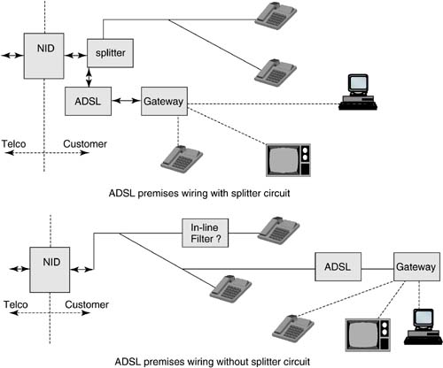
3.6.1 Customer Premises Wiring IssuesCustomer premises wiring has become important for ADSL with the advent of splitterless service. Figure 3.17 shows two internal wiring configurations for a residence. In the first, a splitter appears near the entry to the home, separating the internal POTS network from the ADSL network. The ADSL modem is on a separate wire that is often well maintained and free of further serious transmission degradation. Often this modem is close to the splitter and may be a part of a home gateway that serves as a bridge to CAT-5 quad internal wiring, coaxial cable, wireless LAN, or possibly combinations thereof, premises distribution. An alternative that is actually the dominant installation of ADSL today is the splitterless configuration also in Figure 3.17. In this case, the ADSL modem is in or near the PC and is simply used as an upgrade to earlier voiceband modem internet connection (indeed the modem may have v.90 or v.92 backward compatibility). At or near the personal computer (PC) can be a router (Ethernet, USB, or possibly other) that passes signals to the PC and possibly to other PCs or application devices (i.e., Internet telephones, televisions , etc.) within the home. Alternatively, the modem may be internal to the PC. In any case, the second configuration is simpler for installation by the customer, but allows the ADSL signals to be subject to internal wiring that may have bridged taps, flat-pair with increased noise power spectral densities , phone-on/off-hook transients, and greater attenuation. Thus, the range of the ADSL system from CO to CPE may be reduced because of the internal-wiring at the CPE end that reduces performance margins. Redistribution of signals to other application devices within the CPE may occur on the same twisted pair at frequencies above the ADSL band , which is sometimes known as HomePNA (home phone network alliance) or G.pnt in the second configuration. Figure 3.17. Customer premises wiring options. The advantage of splitterless is the ease of customer installation, which cannot be underestimated in terms of impact on cost and desirability of service. The disadvantage is the harder transmission path , resulting in a lower data rate. The design of splitters was previously treated in [1]. Since that time, so-called in-line filters have been standardized [26]. An in-line filter is a two-way low-pass filter that is installed at or near each (and hopefully every) telephone that shares the same line as ADSL. The in-line filter protects the phone from the upper frequencies used by ADSL and also prevents the higher-frequency impulse like noise from ring and on/off hook transients from entering the ADSL modem. The in-line filter also often can be used at the customer's point of access to "hide" internal bridge-taps, noises, and attenuation if the modem is also placed there. If the modem is still placed deep within the premises, the in-line filter does not hide these effects. This subsection proceeds by investigating some of the more pronounced issues with internal-premises wiring, starting with bridged taps, then premises noises, and signal propagation loss. Bridged TapsBridged taps were modeled in [1] and are discussed at length in [1] and Chapter 7. There are two basic propagation issues with the bridged tap: signal loss and reflections. Signal loss is a simple concept: the energy traversing the phone line from the central office is divided at the bridged tap position. Half the energy remains on the line and half goes into the bridged-tap section of the line. If the bridged-tap is terminated in the 100 Ohm characteristic impedance of the line, then half the energy is lost each time a tap occurs. So, several terminated taps before the ADSL modem could result in severe signal loss, for instance, 3 terminated taps before the modem corresponding to three extension phones would mean a factor of 8, or 9 dB, of signal loss. However, usually taps are not terminated and instead are an open circuit at higher frequencies, meaning that the signal energy is reflected. The reflected energy has a delay at any frequency with respect to the energy at the same frequency on the main line. Thus, although some energy does return to the main line (which is good generally for DMT modems as they can collect and use this energy, something in-line filter designers may forget when trying to design the low-pass filter to match line impedance, to the detriment of the ADSL system), the energy may add destructively at some frequencies and constructively at other frequencies, creating a "rippled" frequency characteristic. The characteristic can never exceed in magnitude at any frequency the level that would have been present had there been no bridged tap. Thus, even with in-line filters, bridged taps cause performance loss if they are not "behind" the filter. DMT modems can recover some of the loss (whereas other modems like QAM or PAM often cannot, even with infinite-complexity decision feedback equalizers); there is nonetheless some level of signal loss. This is a fundamental trade-off for splitterless ADSL. Some bridged taps of course occur before customer premises and thus cause signal loss even when splitters are used. Phone companies may elect to cut or remove these bridged-taps when they can find them (see Chapter 8). The longer the bridged tap, the closer the loss will be to the full 3 dB that characterizes the perfect termination case, and also the lower the frequency at which destructive interference occurs (and thus perhaps within the ADSL band). The reflection of a bridged tap is in some sense good as signal energy returns to the line and some will pass to the ADSL receiver with delay. This energy is recoverable, but requires an integrating mechanism in the receiver to recover both first and delayed energy. In DMT, this occurs because of the long FFT block length, that is, the FFT has enough delay in it. However, the TEQ of [1] can also be useful in ensuring that energy delay is appropriately phased so that it is effectively partially contained within a single symbol boundary of the FFT. In QAM and PAM modems, this integration occurs in the feed-forward filter of the DFE (when it is long enough, which can be 10 times longer than is in use in practice for cost reasons). However, fundamentally, depending on the length of the tap and the group , a very deep notch can occur from reflected energy on short bridged taps or those of less propagation attenuation (fatter gauge wires for instance, as in flat wiring). A DMT transmission system will sense the problem and vacate that and adjacent frequencies ”this is optimum and significantly enhances performance. DFEs cannot implement the same effect and will suffer performance loss. Overall, DMT ADSL has some degree of capability to work with reasonable numbers of bridged taps on most lines, thus enabling splitterless DSL operation. However, bridged taps do reduce performance even in the best of situations, and so fewer taps means higher data rates and reliability of the DSL connection. Radio Noise IngressMany homes use flat-pair internal wiring on telephones. Without twisting, radio noise is more easily coupled into phone lines within customer premises. The effect is similar to the bridged tap, except there is no signal loss (other than the propagation loss of the flat pair itself), in that the signal-to-noise ratio reduces at the radio frequencies of AM broadcast (or other less well-known) signals in the vicinity of the phone line. Some signals will couple much more strongly than others depending on the geometry of the radio antenna and the relative orientation of the phone line. The proper solution in this case, theoretically and implemented in DMT ADSL, is to turn off the bands that correspond to the radio signal. This happens automatically in the DMT modem. [15] Such silencing thus reciprocally protects radios in the vicinity of the phone line from egress/emissions of DSL signals. It is usual for ADSL lines to see 2 “3 AM radio signals that are sufficiently strong to cause silencing of a few tones each of the DMT ADSL signal.
Impulse Noise on CPEImpulse noise couples better into flat pairs than into twisted pairs, and thus can be increased in amplitude within customer premises. Also sources of impulse noise are often within the customer premises and close to internal wiring (e.g., phone lines in an elevator shaft close to magnetic or electric motors that generate noise, refrigerator motors, dimmer lights, etc.). Impulse noise has been previously discussed, but splitterless operation increases such noise and its performance reducing effects. Propagation LossCustomer premises wiring is simply an extension of the phone line and thus additional loss occurs from attenuation, with highest frequencies attenuated most on average. Customer premises wiring can sometimes be up to 1,000 feet, which may lead to as much as 6 dB of additional signal attenuation. This occurs even in systems with splitters. Many in-home telephone lines use PVC insulation that has very high attenuation at high frequencies. This causes additional loss. Repeatered ADSLSome companies have investigated ADSL repeaters within CPE ”with the cost of ADSL modems presently being very low, it is possible to simply cascade two of them at the premises entry. The signals are effectively "repeatered" at that point. Other companies simply try to amplify electronically the ADSL signal as it enters CPE before the signal undergoes addition of any additional noises (impulse, radio) or sees the signal loss of bridged taps or long internal lines. Other companies have designed ADSL repeatered remote terminals that effectively concentrate ADSL modems as well for remote regions where ADSL lines may be much longer than normal. These repeatered modems are sold to telephone companies rather than to the customer directly. 3.6.2 Wired and Wireless Home Gateways and DistributionMany companies today have focused on what is called the home or CPE gateway. A gateway is simply another name for a router where one network, namely, the ADSL network, is connected to one or more networks within the CPE. These other networks may be Ethernet on CAT-5 (or CAT-7) wiring, coaxial cable, wireless, or may even reuse the existing copper . Some have even considered using power lines. The gateway contains the physical-layer modems as well as higher-layer routing of the application signals and conversion into a format that the DSLAM on the CO side can decode and appropriately send to the proper service interface (class 5 switch, Internet service provider, video service provider, etc.). Two more dominant means of distribution of signals within CPE have emerged. Ethernet today runs at 10 Mbps (10BT), 100 Mbps (100BT) and 1000 Mbps (Gig Ethernet) on cat-5 wiring. Typically, the cable is well designed, has little interference or emissions, and relatively low crosstalk. Simple transmission is used at the physical layer and distances are limited to 100 meters . Several locations may branch from the same gateway in a "home-run" (or "star") configuration where each separate device (i.e., computer) has a dedicated physical connection to the router. The customer pays to install (or previously paid to install) the category 5 (or 7) wiring. Typically, this is far less expensive than running any kind of cable (typically fiber) to the CPE. Wiring within the CPE is usually easier because there are existing passage ways for signals under floors, behind walls, or perhaps designed into the structure. Cost of installation may be a few hundred dollars by a professional installer or possibly free if installed by the customer themselves . Ethernet connections and routing mechanisms are well accepted and used by the customer already and somewhat ubiquitous. Thus ADSL-Ethernet bridges/routers or gateways are common. This tends to assume TCP/IP protocol is used on the Ethernet section. Ethernet signals (100 Mbps and 10 Mbps, but not 1000 Mbps) may be sent on coaxial cables also (although that should not be the same cable as for TV systems). Wireless interfaces make use today of the 2.4 GHz-band IEEE 802.11(b) 11 Mbps standardized interface [27] for distribution within premises. This transmission is less reliable and slower than Ethernet and can be affected by the position of the receiver within CPE (much like portable phones work in some locations but not others). The IEEE 802.11(a) standard [28] is increasingly of interest in the less-crowded 5 GHz transmission band, and can transmit to 55 Mbps and possibly beyond. Reliability issues in 802.11(a) and low-speed in 802.11(b) have led to the formation of an 802.11wng group that will standardize multiple-antennae wireless LANs with speeds to 500 Mbps. The gateway allows a number of application devices to share DSL, thereby amortizing the cost of the ADSL service deployment and modems over the various application service fees. For example, a voice-over DSL service could be shared by several neighbors in the vicinity of a phone line with ADSL service, with wireline or wireless distribution of the POTS signals. Then the cost of the single ADSL service provides a mechanism to have significantly higher revenue than might be provided by a single customer. Clearly the same is true of the high-speed Internet service, or possibly even a video service. Such sharing may be particularly accelerative of DSL demand and particularly effective in crowded population areas and hotels. 3.6.3 Central Office Wiring IssuesCO wiring is simpler than the customer premises, but still complicated by ADSL's splitter. Figure 3.18 shows the main distribution frame in the central office (or remote CO terminal) where lines are essentially connected and reconnected to DSLAM (or POTS switch) connections. Where one connection on the MDF was necessary for POTS, now three occur for ADSL and POTS. Additionally, space for the splitters has to be provided. Some companies have investigated DSLAMs that also accepted digital POTS inputs and convert on the ADSL modem card the mu-law or A-law digital POTS signals to analog and then combine them with the ADSL signals (perhaps in a single DAC) for transport. Thus, the MDF needs only one connection, although clearly the POTS switch now needs to be connected to the DSLAM somehow, presumably through high-speed fiber interface that aggregates all the digital POTS signals for the lines shared with the ADSL service by the DSLAM. Figure 3.18. CO wiring configuration with splitters. Digital POTS service within ADSL has become increasingly of interest and eliminates some of the wiring issues at both CPE and CO end and is discussed in the next section. There are also new MDF solutions that integrate splitters and thereby reduce CO wiring. |
| Top |
EAN: 2147483647
Pages: 154
- The Second Wave ERP Market: An Australian Viewpoint
- Context Management of ERP Processes in Virtual Communities
- Data Mining for Business Process Reengineering
- Intrinsic and Contextual Data Quality: The Effect of Media and Personal Involvement
- Development of Interactive Web Sites to Enhance Police/Community Relations