1.2 DSL Reference Model
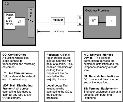
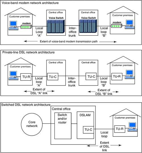
| As shown in the generic DSL reference model in Figure 1.1, a DSL consists of a local loop (telephone line) with a transceiver at each end of the wires. The transceiver is also known as a modem ( modulator /demodulator). The transceiver at the network end of the line is called the line termination (LT) or the transmission unit at the central end (TU-C). The LT may reside within a digital subscriber line access multiplexer (DSLAM) or a DLC-RT for lines fed from a remote site. The transceiver at the customer end of the line is known as the network termination (NT) or the transmission unit at the remote end (TU-R). Figure 1.1. DSL Reference Model The majority of DSLs are served via copper lines extending all the way from the central office to the customer's premises as shown in Figure 1.1. To address DSL's limited line reach, a repeater may be placed near the midpoint of the copper line to boost the signal on the line. However, installation of midspan repeaters has a high material and labor cost. More often, DSL service for customers in areas distant from a CO have DSL service enabled by the placement of a DLC-RT in their neighborhood as shown in Figure 1.2. The DSL signals traverse the relatively short copper wire between the customer and the DLC-RT. The link between the CO and DLC-RT is usually optical fiber. Alternatively, distant areas may also be served via a DSLAM located at a remote site; sometimes the DSLAM may be located within a building having many customers. Figure 1.2. Digital Loop Carrier Reference Model Figure 1.3 shows the network architectures for a voice-band modem, private-line DSL, and switched DSL services. The voice- band modem transmission path extends from one customer modem, a local line, the public switched telephone network (PSTN), a second local line, and a second customer modem. In contrast, the extent of DSL transmission link is a customer-end modem (TU-R), a local line, and a network-end modem (TU-C), with the digital transport through the remainder of the network being outside the scope of the DSL transmission path . The private-line service is not switched within the network and thus provides a dedicated connection between two endpoints. The private-line architecture may contain a service-provisioned cross-connection within the central office. The switched DSL service permits the customer to connect to many end points simultaneously or sequentially. Often, the TU-C for the switched DSL service resides within a DSLAM. The switching or routing functions may reside within the DSLAM or in separate equipment. Figure 1.3. Comparative Network Architectures |
| Top |
EAN: 2147483647
Pages: 154