MPLS Multicast VPN Overview
| MVPN enables a service provider to transport his multicast traffic across MPLS packet-based core networks for IP VPN customers and to implement the "ships in the night" approach with MPLSthat is, the coexistence of separate routing constructs. The SP does not participate in customer multicast routing, and the MVPN configuration is performed only on the PEs, allowing for transparency of the SP network. Some key components of MVPN include:
The two additional components used in a Cisco implementation are as follows:
So, an operation of MVPN can be summarized as follows. An MVRF is assigned to an MD, and a P-group address is defined for each MD. This P-group address must be unique, and C-packets are encapsulated on the PE routers and sent on to the MDT as P-packets. The encapsulation can be GRE/IPinIP/MPLS. An IP source address is the address of the MBGP update, whereas the group destination address is the P-group address. One state exists in the core for all multicast states within a VPN, therein providing core stability. PIM is a soft-state protocol, so a limited number of states can be supported. However, traffic replication is not optimal because the PE routers without interested receivers still receive all multicast traffic per VPN. This architecture solution does not depend on MPLS as the delivery vehicle, and the current solution permits multicast VPNs within one BGP domain. This architecture also depends on stable multicast routing being enabled in the provider core, which is beyond the scope of this chapter. Therefore, from a functional standpoint, IP Multicast can be packaged into three solutions. The first of these solutions is Campus multicast or Intradomain Multicast where there is an end station management, or host to router protocols (IGMP), which requests admission to join or leave multicast groups. The second component of this solution is switch membership management via CGMP or IGMP snooping. This ensures that the switch intelligently handles multicast forwarding without flooding the network. The third component is PIM Sparse Mode, which ensures that the network has appropriate information necessary to forward multicast packets down a multicast distribution tree from source to destination. Note also that an Internet Multicast tree includes MBGP for AS to AS multicast routing information and MSDP for third party source discovery across PIM Sparse Mode clouds as shown in Figure 10-3. Figure 10-3. End-to-End Architecture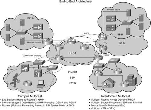 Multicast VPN Operational DetailsIn MVPN, the P routers form a PIM adjacency with each other; this is a global adjacency. The CE router forms a PIM adjacency with the VRF instance on the PE router. A per-VPN multicast distribution tunnel is established between PE routers in a provider network, and the PE routers form PIM adjacency with other PE routers over a tunnel. This is a VRF-specific adjacency. Multicast packets from CE routers are forwarded over the multicast tunnel, and the PE is always a root (source) of the MDT. The PE is also a leaf (receiver) to the MDT rooted on the remote PEs. The MDT creates an any-to-any distribution tree. Figure 10-4 summarizes the MVPN concept. Figure 10-4. Multicast VPN Solution Concept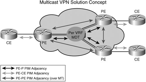 For PIM requirements, the service provider might have a preference for a particular PIM mode or already have multicast deployed in the core. Additionally, a VPN customer might have a preference for a PIM mode or already have deployed multicast in its network. Therefore, the customer-facing solution must support all PIM modes. Available PIM modes are as follows:
PIM-DM is not suitable for service provider core usage because of its scalability limitations and is therefore not supported as a protocol in the core; neither is any other protocol that is not based on PIM (such as dvmrp, mospf, and so on). For a multicast VRF (MVRF) configuration, the MVRF is created when multicast routing is enabled for that VRF. Multicast protocols such as IGMP and PIM are configured and operate in the context of an MVRF. In fact, PIM-SM is favored by most SPs today for the core. The MVRF contains the multicast routing information only for the VRFs that comprise a multicast domain. Figure 10-5 depicts the PIM adjacency relationships for the deployment of MVPN. Figure 10-5. Multicast: PIM Instances and Adjacencies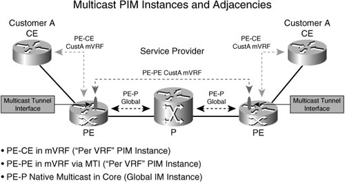 For reverse path forwarding (RPF) considerations, no unicast routing protocol runs over the MDT; therefore, RPF checks need to use other means. For example, the RPF neighbor is determined by checking the BGP next-hop (PE) address to the customer source and the PIM adjacency with the next-hop customer (C) addresses is conveyed by the VPNv4 BGP updates between PEs. For the RPF interface check to succeed, a packet must come in over the RPF interface to the source. One of two scenarios is possible:
When the PE router receives an MDT packet, it performs an RPF check. During the transmission of the packet through the provider network, the normal RPF rules apply. However, at the remote's PE, the router needs to ensure that the originating PE router was the correct one for that CE. It does this by checking the BGP next-hop address of the customer's packet's source address. This next-hop address should be the source address of the MDT packet. The PE also checks that a PIM neighborship with the remote PE exists. A unique group address is required to be used as the MDT for each customer. A unique source address for the multicast packet in the provider network is also required. This source address is recommended to be the address of the loopback interface, which is used as the source for the IBGP, because this address is used for the RPF check at the remote PE. If the provider uses MDT-data groups, these also need to be configured. These MDT-data groups must be unique for each customer. The PE routers must have a PIM adjacency to each other. No other routing protocols can use these MTIs. PE routers are the only routers that need to be MVPN-aware and able to signal information to remote PEs regarding the MVPN. It is therefore fundamental that all PE routers have a BGP relationship with each other or directly or via a route reflector. The source address of the default-MDT is the same address used to source the IBGP sessions with the remote PE routers that belong to the same VPN and MVRF. When PIM-SSM is used for transport inside the provider core, the PEs indicate that they are MVPN-capable and provide for source discovery via this BGP relationship. This capability is indicated by the updated BGP message. When a PE receives a BGP update, which includes the RD and group information, it joins the root of that tree, thereby joining the MDT. The RPF check on the PE is satisfied when the following conditions are met:
In summary, while preserving state inside the core network, no upgrade of the core routers is necessarythus facilitating the deployment of MVPN. However, multicast does need to be deployed in the core. You need to remember that the customer's IP multicast network has no relationship to the provider's multicast network. From the perspective of the provider, the customer's IP multicast packets are merely data to the provider's distinct IP multicast network. |
EAN: 2147483647
Pages: 162