Chapter 1: Introduction
|
|
Communications systems include many devices ranging in complexity from small handheld phones to large, central office switching devices. The earliest communications devices, such as phones, were all electrical and did not possess software, but new communications devices incorporate software based on the function that each device performs in the network. For example, a cellular phone has a microprocessor running a protocol stack to communicate with the cellular network. Frequently, it has additional capabilities, such as the ability to download software upgrades from the network or connect with the Internet.
Understanding issues common to communications equipment is the first step in developing a communications software strategy. Hardware variations then need to be considered in relation to these common issues. In some systems, the size of the code may play a more important role than performance, while in others, complete protocol functionality may not be required. Through a review of the Open Systems Interconnect (OSI) seven layer model, this chapter provides an introduction to the various types of communications systems and specifies a context for the software functions for each of these layers.
1.1 OSI Reference Model
The Open Systems Interconnect (OSI) model (see xrefparanum) was created by the International Organization for Standardization (ISO) to form the basis for communications systems. The OSI seven-layer model for communication protocols provides a modular separation of functionality into seven layers, which can be implemented in hardware and/or software. Each layer works independently, yet builds upon the lower ones.
The seven-layer model is useful for educational and comparative purposes, but most real-world implementations deviate somewhat to accommodate specific application requirements.
Each of the seven layers implements a specific communications function. This logical division allows for modular development, ease of upgrades, and increased manageability, as shown in xrefparanum.
| Layer | Typical Implementation | Name | Function | Examples |
|---|---|---|---|---|
| 7 | Software | Application | Network interface and user apps. | |
| 6 | Software | Presentation | Data format | XDR (eXtended Data Representation) in Network File System (NFS) protocol definition |
| 5 | Software | Session | Dialog and synchronization management | Checkpointing protocols |
| 4 | Software | Transport | End-to-End Application Transport | User Datagram Protocol (UDP), Transmission Control Protocol (TCP) |
| 3 | Software and Hardware | Network | Addressing and packet transmission | Internet Protocol (IP) |
| 2 | Hardware and Software | Data Link | Frame transmission across link | Ethernet MAC |
| 1 | Hardware | Physical | Transmission method | RS-232 |
Each layer is implemented via a combination of end points and protocols. An end point is a device that implements a protocol function. It communicates with a peer end point using the implemented protocol. For example, two hosts using the Transmission Control Protocol (TCP) to communicate between each other are TCP peers (Layer 5 peers, as depicted in xrefparanum). Similarly, a router and a WAN switch communicating over a Frame Relay (FR) link are FR peers.
The following sections will discuss each of these layers, with specific emphasis on the software aspects.
1.1.1 Physical Layer
This layer defines how transmission media, such as cable, communicate with other devices and how bits are conveyed between peer systems. The physical layer provides the hardware means for transmitting data, including mechanical, procedural, electrical, and functional specifications for attributes such as voltage levels, encoding formats, and signal pins. This layer is almost always implemented in hardware; functionality for the physical layer is usually enabled in software as device drivers.
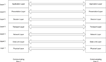
Figure 1.1: OSI Reference Model and Communication between Peers.
1.1.2 Data Link Layer
The physical layer is inherently unreliable-its susceptibility to electrical noise being one of the reasons. The data link layer provides for reliable transmission of frames between peer nodes. As with the physical layer, the peer node is a physically adjacent node. The data link layer is subdivided into two layers-the Logical Link Control (LLC) layer and the Media Access Control (MAC) layer. The data link layer is usually associated with data integrity through error detection and uses data checks such as Cyclic Redundancy Check (CRC). Framing and CRC are handled by hardware controllers; so the data link layer software needs to program the controllers appropriately, as with the physical layer.
Other functions may need to be implemented completely in software, with the hardware controller used only for the framing. For example, a data link layer protocol such as link accessin ISDN (Integrated Services Digital Network) networks is a Layer 2 protocol.
1.1.3 Network Layer
This layer is responsible for delivery of packets from the source to the destination. It isolates the network topology from the higher layers, so that these layers are network independent. The network technologies may be different-for example, the source may be connected to an Ethernet network, while the destination may be part of an ISDN network. The network layer provides information for source and destination addresses, subnet information, and parts used by higher transport layers. This layer uses information to determine the correct path to reach a destination from the source and proceeds with forwarding the packets from source to destination networks.
Routers and software used by routers typically utilize the network layer.
Internet Protocol (IP) is an example of a network layer protocol. It is a connectionless protocol, in the sense that individual packets (datagrams) can be treated differently-for example, each packet can potentially follow a different path from source to destination, depending upon the forwarding decision at each router.
While network layer forwarding can be implemented in either software or hardware, routing is usually less performance critical and involves more peer transactions. Therefore, routing is usually implemented in software.
1.1.4 Transport Layer
Running on top of the network layer, the transport layer provides network-independent, end-to-end integrity between two devices communicating through the network. It builds on the addressing protocols implemented in the network layer and interfaces with higher layer processes and applications on both source and destination systems. Protocols at this layer may be either connection oriented and reliable or connectionless and unreliable.
A connectionless transport protocol, such as User Datagram Protocol (UDP), does not provide feedback from the receiver and can be unreliable. A connection-oriented protocol, such as Transmission Control Protocol (TCP), provides feedback on the reception of the data by the peer. A connection process is initiated prior to data transmission, an acknowledgement is sent upon receipt of the data, and error detection and recovery routines ensure the data arrives intact. The connection is closed when the transmission is complete. For these capabilities, TCP is considered to be reliable.
Transport layer functions are usually implemented in software, except for architectures that support a large number of connections. In this situation, an off-CPU adapter or dedicated chip may be used for handling processing-intensive TCP functions, including data movement. Often TCP Offload Engines (TOE) are used in large-scale communications systems to move processing away from the server. To the higher layers, the TCP interface is preserved, but the actual implementation of TCP uses hardware.
1.1.5 Session, Presentation and Application Layers
The session, presentation, and application layers are closest to the user applications and can be treated together. Session layer functionality includes establishment, management, and termination of application connections and includes services such as data flow synchronization, partitioning, and checkpointing. The presentation layer specifies how user applications format data between applications and includes functionalities such as encryption, data compression, and character sets. The application layer provides end- user services such as mail, file transfer, and so on.
The TCP/IP world uses only one layer-the application layer-to signify all of these, even though the OSI model specifies each of them as separate layers. Hence, the TCP/IP model is a five-layer model. Protocols like Simple Mail Transfer Protocol (SMTP), File Transfer Protocol (FTP), and Virtual terminal protocol (Telnet) are in the application layer. These layers are usually implemented as networking applications on the communications system, but some functions, such as encryption algorithms, may run in an off- CPU hardware accelerator for security or performance reasons.
1.1.6 Networking Communication
Individually, each layer implements a specific communication function that is modular and independent of other layers. Network communication processes data from the bottom of the OSI model with peer devices in the same layer. For example, the physical layer of device A will communicate with the physical layer of device B. So is the case for the data link layer, but the data link layer has to use the services of the physical layer to communicate with the data link layer on device B. Attached headers and trailers encapsulate data and provide a communication path from layer to layer.
From an encapsulation perspective, the lower most layer is the outermost encapsulating scheme (see xrefparanum). For example, in the case of TCP traffic over Ethernet, the data is first encapsulated with the TCP header (Layer 4), preceded by the IP header (Layer 3), which, in turn, is preceded by the Ethernet header (Layer 2).
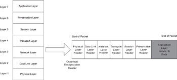
Figure 1.2: Layering Encapsulation for a packet in the OSI Seven Layer Mode
|
|
EAN: 2147483647
Pages: 126