Sequential Assignment
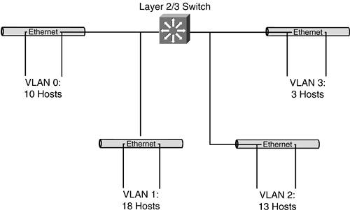
| The most logical approach to use when managing an address space is to assign ranges of host addresses in a sequential fashion. This approach is sometimes referred to as a right-to-left bitwise approach, because you assign blocks from the lowest end of the address range first (using the rightmost bits) and progress in sequence to the higher numbers (moving toward the leftmost bits) in the address space. Strengths and WeaknessesThere are many benefits to using this simple approach to address assignment. It's eminently logical and easy to follow. Those are important attributes if you inherit someone else's hostmaster responsibilities, or if you hope to someday pass the torch to someone else. Perhaps the greatest benefit of this approach is that it is very easy to see how much of your total address space remains unassigned. It is all numerically contiguous at the high end of your address block. Also, not much effort is required to figure out which block to assign nextit's always the next chunk of available address space. The single greatest drawback of the sequential approach is that you lock yourself into the size of block you assign. You can plan for growth (architectural and/or bitmask rounding can work well here), but that growth is limited when you assign the next address space. Thus, it is imperative to size these network blocks correctly as you assign them. If you are adhering strictly to a sequential assignment of address space, accommodating growth in excess of the original surplus in any given assigned block of addresses requires you to migrate that user community to a new address space. This isn't likely to improve your customers' satisfaction levels. You can guard against this by planning for growth with each address block you assign from your network block. But, as we discussed at the beginning of this chapter, trying to plan for growth can have adverse effects. If you build in too much room for growth, you are wasting space. After reviewing the strengths and weaknesses of this approach, it is easy to understand why it is really of most use in situations where little to no future growth is expected. Realistic ContextPerhaps the best way to solidify the concept of sequential address assignment is to examine what a hostmaster's records might look like in such an environment. Figure 14-1 shows a small network that correlates with a hostmaster's records. This sample network is a /24 block that serves a small business campus. The heart of the campus network is a single device that functions as a Layer 2 and 3 switch. Each of the four individual LANs consists of a single Layer 2 distribution switch, and all are defined as virtual local-area networks (VLANs) on the Layer 2/3 switch. Each VLAN is relatively small (a simplifying assumption) and connects to a single switch dedicated to a single workgroup. Figure 14-1. Sample Network for the Sequential Assignment of Addresses
Table 14-1 shows the sequential progression of addresses as you parse address blocks carved out of your network address block. To make it easier for you to see the effects of the CIDR mask (the /number), the bits in the address that are used to identify the network are bold. Please note that this example, while not necessarily implemented in the most clever or appropriate way, is quite serviceable. Whether it proves extensible remains to be seen.
Our sample network features four VLANs for user communities and another block of addresses used for LAN management ports on the Layer 2/3 switch, as well as the distribution switches. Arguably, the network block assigned for this purpose is oversized. It features a /28 with 14 usable addresses when all that is needed is just four addresses (one for each of the switches). It doesn't seem likely that this network block will be outgrown any time soon, but it is important to recognize the interdependencies between this group of addresses and the other VLANs. Each VLAN currently consists of a single switch, but growth will inevitably require another switch to connect the new users and/or devices. That new switch will require an address for its management port, or you won't be able to monitor it or manage it remotely. Adding new VLANs imposes a similar requirement on this LAN management port group of addresses. Regardless of the reason for adding a switch, each new one that is introduced requires a host address from this group. So, if there were any group you were going to oversize, this would be a good candidate. The next thing you should notice is the four VLANs themselves (numbered 0 through 3). Table 14-2 summarizes the number of addressed devices in each VLAN, the number of available device addresses (not counting the reserved host address values), and the remainder. A quick look at this table reveals how much (and how little) room for growth really exists.
You can readily see that the network's greatest exposure lies within VLAN 2. This VLAN has only a single available address within its mathematical range. If that community needs to add two more devices, it will have to renumber all its addressed devices to the addresses remaining unassigned in the high end of the address space. An alternative solution also exists. Because VLAN 3 contains just three devices, it might be easier to migrate those users and their devices to a new address space and simply expand VLAN 2 by changing its mask to a /27. Table 14-3 demonstrates the effects of network address assignments within this network, assuming that you expand VLAN 2 to a /27 network and move VLAN 3 to the next available block of addressing.
One of the very subtle, but critical, aspects of this table that you should take the time to appreciate is its symmetry. Remember Chapter 6, "Classless Interdomain Routing (CIDR)," when we looked at the symmetry of subnetting? Essentially, we said that there were two /28s in each /27 and two /27s in each /26. Well, this table maintains this symmetry. The first three network blocks assigned equal a /26 (a /27 plus two /28s). Consequently, all network assignments after this begin on even bit boundaries. Stated differently, there is no encroachment from network to network. Later in this chapter, we'll look at how this example could be butchered through lack of planning and foresight, with potentially catastrophic effects on the user base. |

EAN: 2147483647
Pages: 118