The Supporting Components
| |
The Supporting Components
Even with the previous components of switch OS and its multitude of functions, there are yet additional supporting components that have become increasingly important to the SAN software. The following are critical to SAN configuration and operation:
-
Data sharing Still problematic because a global file system operating across a set of servers doesnt yet exist. Although some existing software products can be employed, they provide an increased level of latency in switch processing and external server processing. They also require additional hardware resources which provide a centralized locking mechanism.
-
Device sharing Less problematic than data sharing, device sharing can be used effectively to some degree in homogenous environments (for instance, in all Windows servers). By allowing the devices to be controlled by the operating system, they will not be able to communicate altogether effectively.
-
Management This continues to evolve as a discipline. Because SANs are still a new technology, no ones quite sure what to manage, or what to look for, actually. Problem uniqueness, driven by the overwhelming configuration options, thus makes management a site-specific discipline.
-
ISL functions The Achilles heel of SANs. This type of implemented configuration drives interswitch communication. Core -edge configurations, meanwhile, demonstrate different switch-to-switch communications than cascading configurations. As additional hops are needed from switch to switch, processing latency builds, and performance becomes non-linear with respect to resources applied (see Chapter 1).
Device Sharing
One of the first dilemmas faced in working with SAN hardware is sharing devices within the fabric. Device sharing frustration rivals the initial learning curve of setting up network fabric, connecting the devices in the SAN, or even coming up with a suitable cabling strategy. Device sharing requires the knowledge of switch software, HBA parameters, and OS storage access.
The problem boils down to sharing devices between operation systems. NAS environments provide this level of sharing because they separate the native I/O from the application infrastructure (see Chapter 20 for additional information on the differences between SAN and NAS I/O operations). This separation does not happen in SAN configurations. The servers communicate through native I/Os (say, block I/O requests ) with the storage devices. This makes the switch, and the switchs operating system, the fundamental global access supervisor in which the storage administrator is used as the key in establishing who can access what.
Although this could be construed as a hardware function, device access within the switch fabric is handled through the configuration parameters of the switch OS. This is known as zoning , a control function that specifies at switch startup time and device initialization time what devices the node login can access. This happens logically through a set of port addresses associated with a particular server. When implementing a SAN configuration, careful thought should go into planning the whos who of SAN storage access. Most SAN switch vendors recommend that the user develop a matrix of server-to-storage access required for SAN design and implementation.
Figure 15-4 shows the zoning function in partitioning the storage arrays within a simple SAN structure. Sever A has access to devices on storage array prod and test. Server B, however, can only access QA, with shared access for both occurring through the test array. Zoning, at what is considered the hardware level, restricts the access of one device to another, and becomes further complicated when individual devices within the arrays need to be zoned within the configurations.
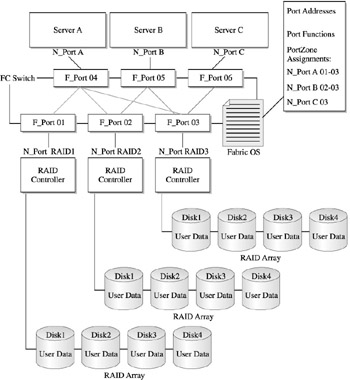
Figure 15-4: Storage device segregation through port zoning
The zoning process requires the mapping of LUN addressing at the server (and, by default, the HBA) level, the array level, and the bridge/router lever, which only makes the whole process that much more complex. Further LUN zones take place within existing zones, something called LUN masking, which masks off access of specific LUNs to the nodes. Operationally, this provides a lower level of device sharing and partitioning within a storage array, or in the context of a tape unit. This process is shown in Figure 15-5, where zoning with LUN masking accommodates further sharing of the QA array along with the installation of the tape drives, which can be used by both servers, though only with specific tape drives.
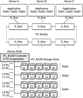
Figure 15-5: SAN configuration with zoning and LUN masking
Data Sharing
Device sharing naturally suggests data sharing. NAS allows a level of sharing because it separates the data from the actual I/O, allowing ownership and access to the data. SAN, however, as we have discussed, provides native access to the data from several servers. As such, data sharing is problematic, to say the least. The major reason is that within a SAN software environment there is no global supervisor to monitor and control access to shared data. As Figure 15-6 shows, through unrestricted access or liberal zoning, two servers can access the same data block for write access, which spells significant data integrity trouble.
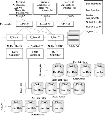
Figure 15-6: SAN configuration using zoning and masking
Data sharing in a SAN environment is tricky, and, depending on the server operating environment, can be assembled using multiple components of the server OS, switch-zoning functions, and LUN masking. This level of complexity within a heterogeneous server OS-SAN environment can be challenging and problematic, given the differences of file access between UNIX and Windows-based operating systems.
There are a handful of commercial software solutions that provide the psuedo-global file manager to monitor and control shared data access. Although these products are becoming more robust, mature, and reliable, they supply an overhead to the processing requests that are subject to data sharing restrictions. Figure 15-7 shows how these products operate in an out-of- band processing mode with the SAN.
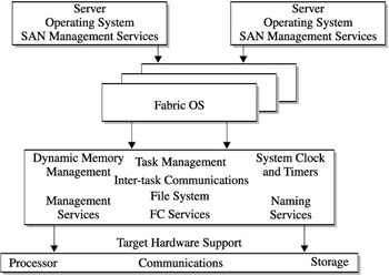
Figure 15-7: Out-of-band processing
SAN Management Applications
While device sharing and data sharing could be considered management applications, they are directed from both the switch OS as well as from external devices, such as attached servers and contollers. These applications run on external devices and only communicate with the switch to obtain specific data for their processing requirements.
This also characterizes a SANs management software components, which are categorized from an external and internal perspective of the switch. Management components are considered out-of-band when processed external to the switch and in-band when their functions process within the switch. Both sets of software, whether in- or out-of-band, access the switch OS for their particular function. As you can see, management functions are quickly becoming imperative to the effective operation of the SAN.
In-Band Management Functions
In-band management functions are distributed within FC switch application functions. However, several provide base functionality, including activities such as configuration and maintenance. Other functions allow add-on type applications, like performance, change, and problem management. Several of the functions generally available through in-band management applications are discussed next . Keep in mind that vendor selection and third-party availability play a key role in what is actually configured in the switch or SAN product set.
Console or Workstation Access Console, or workstation, access is the initial entry to the switch OS, requiring a direct connect console or workstation, and is used in communicating changes through the OS. This interface provides a base-level entry into the initialization and configuration of a SAN fabric, as well as the set up of switch parameters and operating specifications.
Configuration Utility Defining fabrics , assigning worldwide names, domain names , port ID addresses, and IP addresses are just a few of the initial activities performed through the configuration utility console. Others (although vendor-dependent ) include license verification, ISL operation and verification, and FC fabric validation.
The Console Boot Process The console boot process is very important, unless youre installing or operating a single-point SAN. The order in which you reboot the switch operating systems is critical. Most vendors provide some form of boot utility that allows the specification of boot sequencing. Also, given the critical nature of console boot processing, the configuration must be able to provide alternate paths for redundant configurations, such as core/edge installations.
Maintenance Loading new firmware releases will exercise boot processes, given that the operating environment of the switch is no different than any other computer. Most configuration utilities have an integrated function that loads new releases of the switch OS, service patches, and other new or upgraded functions. In some cases, this may be a separate function of an application accessed through the console. However, this brings up an important point of change management, one that is central to OS maintenance in general, and imperative to SANs. The sophistication of this type of management application is just beginning to evolve and change. Management is largely a manual tracking process, albeit an important one (see Chapter 22 for a more detailed discussion of management applications that affect SAN availability).
Monitoring Functions Monitoring functions provide a window in which to view the performance of the SAN components. These same functions can also be accessed through the console and configuration utilities. Like change management, dont expect much. The ability to view port operations is usually on an on-off status level, which can also be done by looking at the port status LEDs. Port activity, in terms of I/O workload performance, is left to third-party tools that process on an out-of-band device. However, ISL operation and status functions can be found with most switch in-band applications. A separate discussion later in this chapter, in the section titled ISL Functions, will cover ISL components.
Out-of-Band Management Functions
Managing the SAN externally will require functions and processes that are executed from attached devices. These, for the most part, will be enabled from attached servers, although some supporting functions will be necessary for functions that bridge, route, or provide an external process. The following discussion highlights some of the major functions that should be considered in design and configuration of SAN solutions. These become critical once the SAN configuration becomes operational.
Configuration Management Configuration management is perhaps the most widely available function, even though its probably the one that does the least. It scans a name server and configuration files on the switch and renders a picture of the total SAN environment. Given additional sophistication, the SAN diagram can become an active diagram in providing a rear view elementary monitor function based on information from the switchs MIB. Added sophistication or no, it is still a rear-view, so theres not a whole lot you can do having used it. (Imagine trying to drive using only your rear-view mirror.) The ability to shield the SAN administrator from the complexities of the line-command configuration utilities or the obtuse nature of the Windows-based GUI is still evolving. Its great for having a pretty picture of the SAN to show your boss, or downloading it to his PC so he can show his boss.
Performance Management Like the other five management disciplines, performance monitoring of the SAN is very elementary. Given the complexities of the switch configuration, fabric software, and diversity of device attachments, this is a difficult task, one that will require additional development and maturity within SAN technology and vendor areas before reaching a real-value proposition. However, I remember what the old IT manager once said about availability of systems information, In the land of the blind, the one-eyed man is king. Given that analogy, any insight into these complexities will provide a piece of the puzzle, which will help accurately manage performance. However, be prepared to manually correlate the information from the application on down to the device.
| Note | Systems management has been categorized into five management disciplines that are used to maintain computer systems regardless of vendor class or technology. These are performance, change, problem, configuration, and capacity management. |
Storage Management Many SAN-specific storage functions that interact with the switch and related software are becoming increasingly availablefor example, storage applications that provide device and disk management solutions like volume managers, disk utilities, and failover solutions. This type of software, in the case of volume managers, executes on the server and interacts through the switch to manage disks into volumes , providing a level of virtualization for applications. Other software products manage the backup/recovery processes that handle data protection strategies. They can also execute on an attached server, and leverage a device-to-device copy operation. Known as server-free or server-less backup, such operations allow the backup application to turn control of the copying operations over to an FC device such as the FC switch. Without the extra resource utilization normally imposed by the controlling servers involvement, the results are a highly optimized data backup operation (see Chapter 22 for more on backup/recovery and the extended copy operation).
Considerations for Integrated Management Functions
Heres the problem. Each application running as an in-band operation on the switchs operating system takes away from the processing dedicated to the operation of the switch, as well as the movement of data within the fabric on behalf of the attached devices. Likewise, any time an out-of-band application accesses the switch, it too takes away from processing power. As Storage Area Networks are very often built with entry-level switches, and continue to experience growth through incremental switch upgrades, supporting applications can easily overrun the switchs operating systems capacity to perform, even at minimum levels. Additionally, as out-of-band applications become more sophisticated and contact the switch with increasingly complex requests, major latency issues are going to pop up with greater frequency. Left unattended, this will put the SAN into a gridlock of overhead versus primary processing responsibilities.
ISL Functions
Interswitch linking (ISL) functions are integral to implementing scalable and highly available SAN configurations. ISL functions are a combination of hardware and software functions, though software functionality quickly becomes the predominant component in enabling switch-to-switch connectivity. Be warned though, ISL functions continue to limit the heterogeneity of configuration flexibility and design due to the proprietary implementation employed by various vendors. The bottom line is that highly scalable multiswitch SAN configurations are best built from homogeneous products.
ISL functions provide a communications link between switches and fabrics, which allows switches to be configured to meet the needs of the I/O workloads they are supporting. Simple cascading connections provide a way of attaching multiple device nodes within an extended fabric, or among disparate fabrics. Figure 15-8 shows the ISL functions required to support a three-switch configuration. The servers I/O requests for switch A are processed through the switch it is directly connected to. If the server requests data from storage array Prod2, though, it has to connect through switch A, then reconnect to switch B through ISL 1 port. The I/O request is then serviced and the response from the Prod2 storage array is sent back along the same route, using ISL 1 to return to the server via switch A.
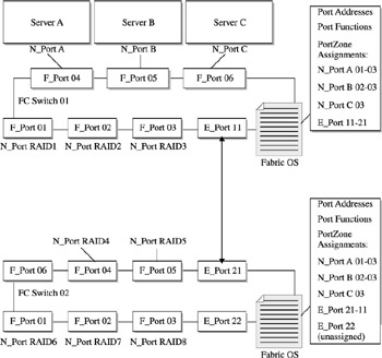
Figure 15-8: ISL functions supporting a simple cascading switch configuration
Taking this a step further, switch C can be accessed via switch A through the ISL 2 port. This configuration continues to expand using ISL functions to provide additional access to storage device nodes. Additional operational characteristics to this switch configuration include dynamic switch configuration, cross connections (also referred to as trunking), fabric recognition, ISL device recognition, and performance.
Many switches support dynamic configurations, where, upon initialization, the switch automatically recognizes and logs in attached device nodes and E_Port ISL functions, thereby identifying the ISL connection as well as the devices connected to both.
In many cases, the use of an ISL facilitates the basic connectivity to other node devices, but may not possess the necessary performance or failover requirements for the workload. Should this arise, multiple ISL functions are paired to facilitate throughput requirements and act as a backup if one ISL port becomes inoperative. This is illustrated in Figure 15-9.
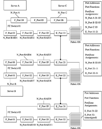
Figure 15-9: ISL supporting higher performance and failover
The final factor is the switchs capability to dynamically recognize storage devices. In many cases, this is performed automatically when the switch configuration is initialized . Sometimes, though, the device nods might drop off and not be recognized by the primary switch, as in cascading configurations. If this happens, caution must be taken in analyzing the requirements for the storage device and the switch through which recognition is passed to the owning server.
| |
EAN: 2147483647
Pages: 192