Address Translation
Now that you've seen how Windows 2000 structures the 32-bit virtual address space, let's look at how it maps these address spaces to real physical pages. We'll describe what happens when such a translation doesn't resolve to a physical memory address (paging) and explain how Windows 2000 manages physical memory via working sets and the page frame database.
User applications reference 32-bit virtual addresses. Using data structures the memory manager creates and maintains, the CPU translates virtual addresses into physical addresses. For example, Figure 7-9 shows three consecutive virtual pages mapped to three physically discontiguous pages.
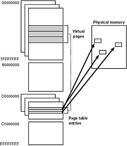
Figure 7-9 Mapping virtual addresses to physical memory
The dashed line connecting the virtual pages to the PTEs in Figure 7-9 represents the indirect relationship between virtual pages and physical memory. Virtual addresses aren't mapped directly to physical ones. Instead, as you'll discover in this section, each virtual address is associated with a system-space structure called a page table entry (PTE), which contains the physical address to which the virtual one is mapped.
NOTE
Kernel-mode code (such as device drivers) can reference physical memory addresses by mapping them to virtual addresses. For more information, see the memory descriptor list (MDL) support routines described in the DDK documentation.
Throughout the remainder of this section, we'll explain the details of how Windows 2000 accomplishes this mapping.
Translating a Virtual Address
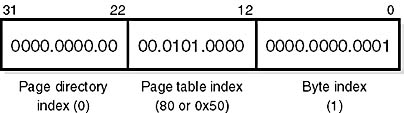
By default, Windows 2000 on an x86 system uses a two-level page table structure to translate virtual to physical addresses. (Systems running the PAE kernel use a three-level page table—this section assumes non-PAE systems.) A 32-bit virtual address is interpreted as three separate components—the page directory index, the page table index, and the byte index—that are used as indexes into the structures that describe page mappings, as illustrated in Figure 7-10. The page size and the PTE width dictate the width of the page directory and page table index fields. For example, on x86 systems, the byte index is 12 bits because pages are 4096 bytes (212 = 4096).
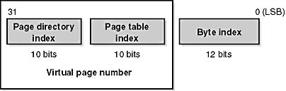
Figure 7-10 Components of a 32-bit virtual address on x86 systems
The page directory index is used to locate the page table in which the virtual address's PTE is located. The page table index is used to locate the PTE, which, as mentioned earlier, contains the physical address to which a virtual page maps. The byte index finds the proper address within that physical page. Figure 7-11 shows the relationship of these three values and how they are used to map a virtual address into a physical address.
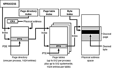
Figure 7-11 Translating a valid virtual address (x86-specific)
The following basic steps are involved in translating a virtual address:
- The memory management hardware locates the page directory for the current process. On each process context switch, the hardware is told the address of a new process page directory, typically by the operating system setting a special CPU register.
- The page directory index is used as an index into the page directory to locate the page directory entry (PDE) that describes the location of the page table needed to map the virtual address. The PDE contains the page frame number (PFN) of the page table (if it is resident—page tables can be paged out).
- The page table index is used as an index into the page table to locate the PTE that describes the physical location of the virtual page in question.
- The PTE is used to locate the page. If the page is valid, it contains the PFN of the page in physical memory that contains the virtual page. If the PTE indicates that the page isn't valid, the memory management fault handler locates the page and tries to make it valid. (See the section on page fault handling.) If the page can't be made valid (for example, because of a protection fault), the fault handler generates an access violation or a bug check.
- When the PTE is pointed to a valid page, the byte index is used to locate the address of the desired data within the physical page.
Now that you have the overall picture, let's look at the detailed structure of page directories, page tables, and PTEs.
Page Directories
Each process has a single page directory, a page the memory manager creates to map the location of all page tables for that process. The physical address of the process page directory is stored in the kernel process (KPROCESS) block but is also mapped virtually at address 0xC0300000 on x86 systems (0xC06000000 on systems running the PAE kernel image). All code running in kernel mode references virtual addresses, not physical ones. (For more detailed information about KPROCESS and other process data structures, refer to Chapter 6.)
The CPU knows the location of the page directory page because a special register (CR3 on x86 systems) inside the CPU that is loaded by the operating system contains the physical address of the page directory. Each time a context switch occurs to a thread that is in a different process than that of the currently executing thread, this register is loaded from the KPROCESS block of the target process being switched to by the context-switch routine in the kernel. Context switches between threads in the same process don't result in reloading the physical address of the page directory because all threads within the same process share the same process address space.
The page directory is composed of page directory entries (PDEs), each of which is 4 bytes long (8 bytes on systems running the PAE kernel image) and describes the state and location of all the possible page tables for that process. (As described later in the chapter, page tables are created on demand, so the page directory for most processes points only to a small set of page tables.) The format of a PDE isn't repeated here because it's mostly the same as a hardware PTE (shown in Figure 7-13).
On x86 systems, 1024 page tables (2048 on PAE systems) are required to describe the full 4-GB virtual address space. The process page directory that maps these page tables contains 1024 PDEs. Therefore, the page directory index needs to be 10 bits wide (210 = 1024).
EXPERIMENT
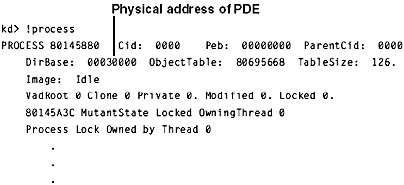
Examining the Page Directory and PDEsYou can see the physical address of the currently running process's page directory by examining the DirBase field in the !process kernel debugger output:
You can see the page directory's virtual address by examining the kernel debugger output for the PTE of a particular virtual address, as shown here:
The PTE part of the kernel debugger output is defined in the section "Page Table Entries" below.
Process and System Page Tables
Before referencing a byte within a page with the byte offset, the CPU first needs to be able to find the page that contains the desired byte of data. To find this page, the operating system constructs another page of memory that contains the mapping information needed to find the desired page containing the data. This page of mapping information is called a page table. Because Windows 2000 provides a private address space for each process, each process has its own set of process page tables to map that private address space because the mappings will be different for each process.
The page tables that describe system space are shared among all processes, however. When a process is created, system space PDEs are initialized to point to the existing system page tables. But as shown in Figure 7-12, not all processes have the same view of system space. For example, if paged pool expansion requires the allocation of a new system page table, the memory manager doesn't go back and update all the process page directories to point to the new system page table. Instead, it updates the process page directories when the processes reference the new virtual address.
Thus, a process can take a page fault when referencing paged pool that is in fact physically resident because its process page directory doesn't yet point to the new system page table that describes the new area of pool. Page faults don't occur when accessing nonpaged pool, even though it too can be expanded, because Windows 2000 builds enough system page tables to describe the maximum size during system initialization.
System PTEs aren't an infinite resource—Windows 2000 calculates how many system PTEs to allocate based on the memory size. You can see how many system PTEs are available by examining the value of the Memory: Free System Page Table Entries counter in the Performance tool. You can also override the calculation made at boot time by setting the registry value HKLM\SYSTEM\CurrentControlSet\Control\Session Manager\Memory Management\SystemPages to the number of PTEs you want. However, the maximum that Windows 2000 will allocate is 128,000 on x86 systems.
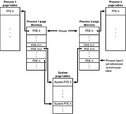
Figure 7-12 System and process-private page tables
Page Table Entries
As mentioned earlier, page tables are composed of an array of page table entries (PTEs). You can use the !pte command in the kernel debugger to examine PTEs. (See the experiment "Translating Addresses" below.) Valid PTEs (the kind we'll be discussing here; we'll cover invalid PTEs in a later section) have two main fields: the page frame number (PFN) of the physical page containing the data or of the physical address of a page in memory, and some flags that describe the state and protection of the page, as shown in Figure 7-13.
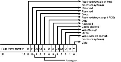
Figure 7-13 Valid x86 hardware PTEs
As you'll see later, the bits labeled Reserved in Figure 7-13 are used only when the PTE isn't valid (the bits are interpreted by software). Table 7-13 briefly describes the hardware-defined bits in a valid PTE.
Table 7-13 PTE Status and Protection Bits
| Name of Bit | Meaning |
|---|---|
| Accessed | Page has been read. |
| Cache disabled | Disables caching for that page. |
| Dirty | Page has been written to. |
| Global | Translation applies to all processes. (For example, a translation buffer flush won't affect this PTE.) |
| Large page | Indicates that the PDE maps a 4-MB page (used to map Ntoskrnl and HAL, initial nonpaged pool, etc.) on systems with 128 MB or more of memory. |
| Owner | Indicates whether user-mode code can access the page or whether the page is limited to kernel-mode access. |
| Valid | Indicates whether the translation maps to a page in physical memory. |
| Write through | Disables caching of writes to this page so that changes are immediately flushed to disk. |
| Write | On uniprocessor systems, indicates whether the page is read/write or read-only; on multiprocessor systems, indicates whether the page is writable. (The Write bit is stored in a reserved bit in the PTE.) |
On x86 systems, a hardware PTE contains a Dirty bit and an Accessed bit. The Accessed bit is clear if a physical page represented by the PTE hasn't been read or written; the processor sets this bit when the page is first read or written. The processor sets the Dirty bit only when a page is first written. In addition to those two bits, the x86 architecture has a Write bit that provides page protection—when this bit is clear, the page is read-only; when it is set, the page is read/write. If a thread attempts to write to a page with the Write bit clear, a memory management exception occurs and the memory manager's access fault handler (described in the next section) must determine whether the thread can write to the page (for example, if the page was really marked copy-on-write) or whether an access violation should be generated.
Hardware PTEs on multiprocessor x86 systems have an additional Write bit implemented in software that is intended to avoid stalls when flushing the PTE cache (called the translation look-aside buffer) across processors. This bit indicates that a page has been written to by a thread running on some processor.
On the x86 hardware platform, PTEs are always 4 bytes (32 bits) in size (8 bytes for systems running with PAE enabled), so each page table contains 1024 PTEs (512 on PAE systems) (4096 bytes per page at 4 bytes per PTE) and therefore can map 1024 pages (512 pages PAE), for a total of 4 MB (2 MB PAE) of data pages.
The virtual address's page table index field indicates which PTE within the page table maps the data page in question. On x86 systems, the page table index is 10 bits wide (9 on PAE), allowing you to reference up to 1024 PTEs (512 on PAE). However, because Windows 2000 provides a 4-GB private virtual address space, more than one page table is needed to map the entire address space. To calculate the number of page tables required to map the entire 4-GB process virtual address space, divide 4 GB by the virtual memory mapped by a single page table. Recall that each page table on an x86 system maps 4 MB (2 MB on PAE) of data pages. Therefore, 1024 page tables (4 GB/4 MB)—or 2048 page tables, 4 GB/2 MB for PAE—are required to map the full 4-GB address space.
Byte Within Page
Once the memory manager has found the physical page in question, it must find the requested data within that page. This is where the byte index field comes in. The byte index field tells the CPU which byte of data in the page you want to reference. On x86 systems, the byte index is 12 bits wide, allowing you to reference up to 4096 bytes of data (the size of a page).
Translation Look-Aside Buffer
As we've learned so far, each address translation requires two lookups: one to find the right page table in the page directory and one to find the right entry in the page table. Because doing two additional memory lookups for every reference to a virtual address would result in unacceptable system performance, most CPUs cache address translations so that repeated accesses to the same addresses don't have to be retranslated. The x86 processor provides such a cache in the form of an array of associative memory called the translation look-aside buffer, or TLB. Associative memory, such as the TLB, is a vector whose cells can be read simultaneously and compared to a target value. In the case of the TLB, the vector contains the virtual-to-physical page mappings of the most recently used pages, as shown in Figure 7-14, and the type of page protection applied to each page. Each entry in the TLB is like a cache entry, whose tag holds portions of the virtual address and whose data portion holds a physical page number, protection field, valid bit, and usually a dirty bit indicating the condition of the page to which the cached PTE corresponds. If a PTE's global bit is set (used for system space pages that are globally visible to all processes), the TLB entry isn't invalidated on process context switches.
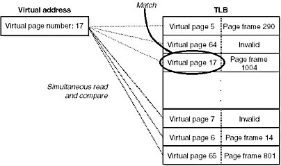
Figure 7-14 Accessing the translation look-aside buffer
Virtual addresses that are used frequently are likely to have entries in the TLB, which provides extremely fast virtual-to-physical address translation and, therefore, fast memory access. If a virtual address isn't in the TLB, it might still be in memory, but multiple memory accesses are needed to find it, which makes the access time slightly slower. If a virtual page has been paged out of memory or if the memory manager changes the PTE, the memory manager must explicitly invalidate the TLB entry. If a process accesses it again, a page fault occurs and the memory manager brings the page back into memory and re-creates an entry for it in the TLB.
To maximize the amount of common code, the memory manager treats all PTEs the same whenever possible, whether they are maintained by hardware or by software. For example, the memory manager calls a kernel routine when a PTE changes from invalid to valid. The job of this routine is to load this new PTE into the TLB in whatever hardware-specific manner the architecture requires. On x86 systems, the code is a NOP because the processor loads the TLB without any intervention from the software.
EXPERIMENT
Translating AddressesTo clarify how address translation works, let's go through a real example of translating a virtual address on an x86 non-PAE system, using the available tools in the kernel debugger to examine page directories, page tables, and PTEs. In this example, we'll use a process that has virtual address 0x50001 currently mapped to a valid physical address. In later examples, you'll see how to follow address translation for invalid addresses with the kernel debugger.
First let's convert 0x50001 to binary and break it into the three fields that are used to translate an address. In binary, 0x50001 is 101.0000.0000.0000.0001. Breaking into the component fields yields the following:
To start the translation process, the CPU needs the physical address of the process page directory, stored in the CR3 register while a thread in that process is running. You can display this address either by examining the CR3 register itself or by dumping the KPROCESS block for the process in question using the !process command, as shown here:
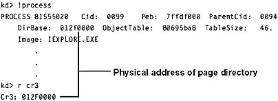
In this case, the page directory is stored at physical address 0x12F0000. As shown in the preceding illustration, the page directory index field in this example is 0. Therefore, the PDE is at physical address 0x12F0000.
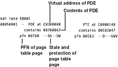
The kernel debugger !pte command displays the PDE and PTE that describe a virtual address, as shown here:
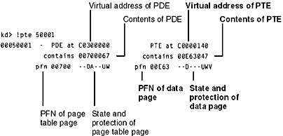
In the first column, the kernel debugger displays the PDE and in the second column the PTE. Notice that the PDE address is shown as a virtual address, not a physical address—as noted earlier, the process page directory starts at virtual address 0xC0300000 on x86 systems. Because we're looking at the first PDE in the page directory, the PDE address is the same as the page directory address.
The PTE is at virtual address 0xC0000140. You can compute this address by multiplying the page table index (0x50 in this example) by the size of a PTE: 0x50 multiplied by 4 equals 0x140. Because the memory manager maps page tables starting at 0xC0000000, adding 140 yields the virtual address shown in the kernel debugger output: 0xC0000140. The page table page is at PFN 0x700, and the data page is at PFN 0xe63.
The PTE flags are displayed to the right of the PFN number. For example, the PTE that describes the page being referenced has flags of D---UWV. D here stands for dirty (the page has been modified), U for user-mode page (as opposed to a kernel-mode page), W for writable page (rather than read-only), and V for valid. (The PTE represents a valid page in physical memory.)
Physical Address Extension
All of the Intel x86 family processors since the Pentium Pro include a memory-mapping mode called Physical Address Extension (PAE). With the proper chipset, the PAE mode allows access to up to 64 GB of physical memory. When the x86 executes in PAE mode, the memory management unit (MMU) divides virtual addresses into four fields, as shown in Figure 7-15.
The MMU still implements page directories and page tables, but a third level, the page directory pointer table, exists above them. PAE mode can address more memory than the standard translation mode not because of the extra level of translation but because PDEs and PTEs are 64-bits wide rather than 32-bits. The system represents physical addresses internally with 24 bits, which gives the x86 the ability to support a maximum of 224+12 bytes, or 64 GB, of memory.
As explained in Chapter 2, there is a special version of the core kernel image (Ntoskrnl.exe) with support for PAE called Ntkrnlpa.exe. (The multiprocessor version is called Ntkrpamp.exe.) To select this PAE-enabled kernel, you must boot with the /PAE switch in Boot.ini.
This special version of the kernel image is installed on all Windows 2000 systems, even Windows 2000 Professional systems with small memory. The reason for this is to facilitate testing. Because the PAE kernel presents 64-bit addresses to device drivers and other system code, booting /PAE even on a small memory system allows a device driver developer to test parts of their drivers with large addresses. The other relevant Boot.ini switch is /NOLOWMEM, which discards memory below 4 GB and relocates device drivers above this range, thus guaranteeing that these drivers will be presented with physical addresses greater than 32 bits.
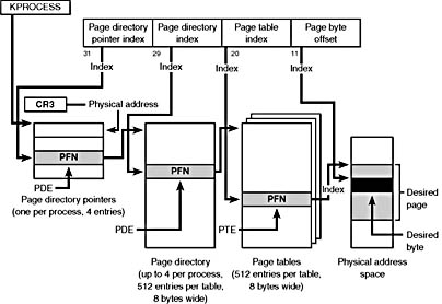
Figure 7-15 Page mappings with PAE
Only Windows 2000 Advanced Server and Windows 2000 Datacenter Server are required to support more than 4 GB of physical memory. (See Table 2-2.) Using the AWE Win32 functions, 32bit user processes can allocate and control large amounts of physical memory on these systems.
EAN: 2147483647
Pages: 121