Lab 7: Ethernet Switching, VLAN Trunking, and Spanning Tree Root Placement ”Part I Practical Scenario Small Ethernet networks, for the most part, are plug-and-play. Even when Ethernet switches are deployed in small networks, they are user -friendly and not much configuration is needed. It is when redundancy is added to the network that things get more complicated. This lab gives you practice in configuring a redundant Ethernet switched networks and the challenges associated with them. Lab Exercise Game LANs, Inc. is a company that provides high-speed backbones for entertainment centers around the country. Game LAN uses Cisco 100-Mbps and Gigabit Ethernet switches to provide the switch fabric for the LANs that the company installs . A part of all Game LAN networks is the redundancy that is built into each design. Your task is to configure a Game LAN network by using the following parameters as design guidelines: -
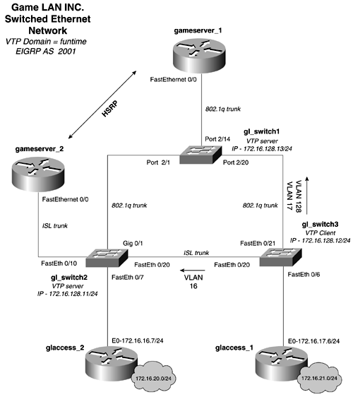
Configure an Ethernet switched network as depicted in Figure 2-39. Figure 2-39. Game LAN Ethernet Network  -
Use the VTP domain name , funtime, for all the switches in the network. -
Create three VLANs on this network, and do not use VLAN1. Create one VLAN for management, which is IP subnet 172.16.128.0/24. Mark this VLAN so that it stands out as the management VLAN when being viewed by other switches. Two other VLANs are needed, one for the glaccess_2 router, 172.16.16.0/24, and one for the glaccess_1 router on subnet 172.16.17.0/24. -
Configure the gameserver_1 and the gameserver_2 routers to route among all the VLANs on the network. All VLANs and IP address should be capable of reaching each other. Use EIGRP as the routing protocol, and use 2001 as the Autonomous System ID. -
Tune STP so that the root for all VLANs corresponds to the HSRP configuration. The root for VLANs 128 and 17 should be gl_switch1, and the root for VLAN 16 should be gl_switch2. -
Configure the gl_switch so that only devices on the subnet 172.16.17.0/24 can Telnet to the switch. -
(Optional) Port 2/24 contains a secure workstation. It has a MAC address of 0000.863c.3b41. Configure this port so that only this workstation will work on it, and shut it down if another workstation is plugged into it. Lab Objectives -
Configure an Ethernet switched network as depicted in Figure 2-39. -
Use a single VTP domain throughout the network. Configure gl_switch1 and gl_switch2 as VTP servers, and configure gl_switch3 as a VTP client. Configure the VLAN trunks and trunk type as denoted in the Figure 2-39. Be sure to configure both types of trunks, 802.1q and ISL. -
Ensure full IP connectivity to all IP interfaces ”that is, be sure that you can ping all LAN interfaces. -
Create three VLANs on this network, and do not use VLAN1. Create one VLAN for management, which is IP subnet 172.16.128.0/24; one for the glaccess_2 router, 172.16.16.0/24; and one for the glaccess_1 router on subnet 172.16.17.0. -
Configure the gameserver_1 and the gameserver_2 routers to route among all the VLANs on the network. For this lab, you will user EIGRP as the routing protocol. Configure HSRP between these routers. Use the first IP addresses on each subnet as the HSRP shared address. For example, subnet 172.16.128.0/24, the management subnet, should use 172.16.128.1 as the HSRP shared address. Configure HSRP so that the gameserver_2 is the primary for the subnet 172.16.16.0/24 and the gameserver_1 router is the HSRP primary for subnets 172.16.128.0/24 and 172.16.17.0/24. All VLANs and IP address should be capable of reaching each other. -
Configure STP so that the root for VLANs 128 and VLAN 17 is gl_switch1 and the root for VLAN 16 is gl_switch2. -
Configure the gl_switch so that only devices on the 172.16.16.0/24 can Telnet to the switch. This can be the only device that can Telnet and manage the switch. -
(Optional) Port 2/24 contains a secure workstation. It has a MAC address of 0000.863c.3b41. Configure this port so that only this workstation will work on it, and shut it down if another workstation is plugged into it. Equipment Needed -
Four Cisco routers with Ethernet interfaces. Two routers must have 100-Mbps interfaces. Recall that you need a minimum of a 100 Mbps to run any VLAN trunking protocol. If you do not have routers with 100-Mbps interfaces, routing also can be accomplished by configuring three Ethernet interfaces to the switch from a single router; one interface would be in each VLAN. -
Three Cisco Catalyst Ethernet switches. This lab was designed specifically for two Catalyst 2900/3500 series switches and one Catalyst 4000/5500/6500 series switch. -
To gain practical experience on each type of Cisco Catalyst platform, both types of switches are used in this lab. The gl_switch1 is in the Catalyst 4000/5500/6500 family, while the gl_switch2 and gl_switch3 are in the Catalyst 2900/3500 series family. The specific type of switch is not that important to the functionality of this lab. Physical Layout and Prestaging -
The networks 172.16.20.0/24 and 172.16.21.0/24 are simulated by loopback interfaces on the glaccess_2 and glaccess_1 routers, respectively. -
This chapter does not focus on the EIGRP and HSRP configurations of this lab. We will show how they are performed during the walkthrough, but for more information on the specifics of how to configure EIGRP and HSRP, see the chapters covering that material. |
