Ethernet Technical Overview
| < Free Open Study > |
| Ethernet is extremely popular, and many fine books and whitepapers have been written on it. For these reasons, we assume that you have some background in Ethernet technology; therefore, this chapter does not cover Ethernet frames, hubs, and cables in any great length. You should become familiar with the different Ethernet frame types, DIX Version II, and 802.2 frames , as well as the different media types used in Ethernet. This chapter instead focuses more on Spanning Tree, Fast Ethernet, Gigabit Ethernet, and Ethernet and Token Ring switching. Ethernet OperationEthernet operates at the OSI Layer 2, the data link layer. The data link layer actually is divided into two sublayers : the MAC layer and the Logical Link Control (LLC) layer. The LLC layer ”802.2, in this case ”is a standardized interface between a hardware-specific MAC and a Layer 3 protocol. The MAC layer has the following responsibilities:
Table 2-2 lists the common physical characteristics of 10-Mbps, 10-Mbps, and 1000-Mbps Ethernet. Table 2-2. Common Ethernet Specifications
Ethernet CSMA/CDEthernet technology commonly is referred to as carrier-sense multiple access collision detect (CSMA/CD). Ethernet transmits frames in the following manner:
Half- and Full-Duplex EthernetEthernet was developed on older coax type cables capable of transmitting or receiving a signal at any given time. This is precisely why Ethernet needed CSMA/CD technology. With the advent of switches, running Ethernet over UTP and fiber, full-duplex Ethernet became available. Full-duplex Ethernet allows a station to simultaneously transmit and receive data. Ethernet frames are transmitted and received simultaneously on two pairs of UTP or fiber at any given time. Full-duplex Ethernet is essentially Ethernet without CSMA/CD. Full-duplex mode basically doubles the bandwidth of Ethernet! To run full-duplex Ethernet, the station and switch both must be capable and configured for full-duplex operation. A hub with multiple stations cannot operate in full-duplex mode. NOTE A station not operating in the correct duplex mode will generate an enormous number of collisions on the port where it is located. These collisions mostly likely will be registered as "late collisions." Be sure that the port on the switch and the end station are operating in the same duplex mode. Fast EthernetIn May 1995, the IEEE adopted the Fast Ethernet standard, 802.3u. Years later, after battling FDDI, 100VG AnyLAN, and ATM, this standard became the prominent type of LAN. As costs per port dropped along with the prices of network interface cards (NICs), Fast Ethernet won out over FDDI and 100VG AnyLAN and ATM for many reasons:
Some important features and specifications of Fast Ethernet are as follows :
Gigabit EthernetThe ink was hardly dry on the Fast Ethernet standard, and the IEEE started to work on the 802.3z, or Gigabit Ethernet, standard. Three short years later, in June 1998, the 802.3z standard officially was adopted. For the most part, the Gigabit standard is the Fast Ethernet standard multiplied by 10. This is why 10-Gb Ethernet products are right around the corner and 100-Gb Ethernet is an eventuality. Some important features and specifications of Gigabit Ethernet are as follows:
One element that makes Gigabit Ethernet one of the most versatile protocols in years is the concept of the GMII. Except for the strictly 1000Base-TX switches, most Gigabit Ethernet switches come with open ports for GBICs. Depending on your network needs, you can put any type of GBIC in this port. With the click of a GBIC, your network can change from a limited 100-m copper -based network to a 10,000-m fiber-based network! The sections that follow cover the more common GBICs, Gigabit standards, and length limitations. 1000Base-SX Gigabit Ethernet1000Base-SX GBICs use a laser-based wavelength of 850 nms. Depending on the cable type, SX GBIC operates at distances of 220 m to 550 m, as listed in Table 2-3. Wavelengths up to 850 nm are visible to the human eye. Table 2-3. 1000Base-SX Cable Limitations
1000 Base-LX Gigabit EthernetLX GBICs use a laser-based wavelength of 1300 nms. Depending on the cable type, LX GBIC operate at distances of 550 m to 5000 m, as listed in Table 2-4. Cisco also supports an LH and LX GBIC, which extends the IEEE 1000Base-LX maximum distance of 5 km. Table 2-4. 1000Base-LX Cable Limitations
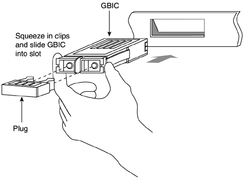
1000Base-CX Gigabit EthernetThe CX standard is for operating Gigabit Ethernet over copper for short distances. 1000Base-CX uses a 150-ohm balanced shielded copper cable. The distance of the CX standard is limited to only 25 meters. 1000Base-T Gigabit EthernetThe IEEE standard for Gigabit Ethernet transmission over Cat 5 UTP is 802.3ab. The standard defines the maximum distance to be 100 meters and the copper to be at least Cat 5 using four pairs of wires, terminated with an RJ-45 jack. Figure 2-1 illustrates a GBIC. Figure 2-1. GBIC Installation NOTE The Cisco Gigastack GBIC is a Cisco proprietary GBIC used on an uplink port to connect Gigabit Ethernet switches. Ethernet AutonegotiationTo simplify the configuration of Ethernet devices, the 802.3.u committee defined Fast Link Pulse (FLP). FLP sends a series of pulses on the network that can deduce what duplex and speed the link is operating at. The station and the hub/switch agree on the highest priority and configure the station in that manner. Table 2-5 lists the priority that FLP uses. Both devices need to support autonegotiation logic for autonegotiation to work. Table 2-5. Ethernet Autonegotiation Prioritization
Infrastructure devices, such as routers and servers, always should have speed and duplex settings fixed. Most 100-Mbps and greater NICs support full-duplex operation. Running at full-duplex mode essentially doubles the capacity of Ethernet. Taking advantage of this is the cheapest network upgrade that you will ever do! NOTE Duplex modes are a function of the hardware built into the network interface card (NIC). Software upgrades will not allow you to run full-duplex mode. For full-duplex mode to work, the station and the switch port must be capable of full-duplex operation. |
| < Free Open Study > |
EAN: 2147483647
Pages: 283
