Timed Portion Lab Rules -
No static routes or floating static routes are used unless specifically stated. -
Follow the instructions exactly. Be careful to propagate routes only where and when instructed. Use the PVCs only as directed by the instructions. -
Primary configurations might need to be modified for Part II only when you are finished with the primary configurations. -
You can use the configuration guides and the Cisco Documentation CD-ROM for your only reference material. -
You have 8 1/2 hours to complete the lab. Do not talk to anyone during this phase. -
It is recommended that you read the entire lab before beginning. -
Make an accurate and precise network illustration. -
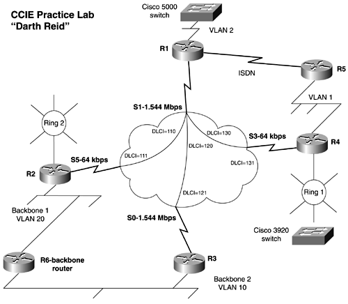
Use Figure 18-4 as reference for the physical layout of the lab. Figure 18-4. Network Diagram for "Darth Reid"  Section I: Basic IP Configuration -
Access server: Configure the access server/router so that all the routers and the switches can be accessed through reverse Telnet. Password-protect all routers and switches with the password cisco. -
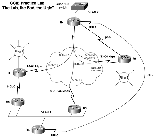
IP address assignment: Assign an IP addresses to all physical interfaces, as denoted in Figure 18-6. Use the major network of 133.10. x.x on all interfaces. Use a 24-bit mask on all interfaces except for the following: Figure 18-6. Network Diagram for "The Lab, the Bad, the Ugly"  R2: Use an IP address of 160.100.2.1/24 on the Ethernet interface; make this VLAN 20. R4: Use a 28-bit mask on the loopback interface, and use a 26-bit mask on the Ethernet interface. R1: Allow for 30 hosts on the loopback interface. Add an additional loopback with the address of 128.200.1.1/24. R3: Use a 25-bit mask on the loopback interface. Use an IP address of 160.100.1.1/24 on the Ethernet interface; make this VLAN 10. R5: Use a 26-bit mask on the Ethernet interface. -
Full IP and IPX connectivity to all Ethernet, Token Ring, and loopback interfaces will be expected unless noted. -
Document the network thoroughly; include all OSPF areas, IP/IPX address, IPX networks, and so on. Section II: Catalyst Configuration -
Connect the R1, R4, and R5 routers to the Catalyst 5000. Connect the two Token Ring routers to the Catalyst 3900 Token Ring switch. -
Configure the Backbone 1 segment and Backbone 2 segment to be in separate VLANs of your choice. -
Configure R1 Ethernet as VLAN 2 on the Catalyst 5K. Configure the R4/R5 Ethernet segment as VLAN 1 on the Catalyst 5K. Assign an IP address in VLAN 2 IP range. -
Configure the Catalyst so that only users on VLAN 1 can access the switch through Telnet. Do not use an access list on any routers to control access to the Catalyst 5K. -
Configure the switch so that all VLAN 2 traffic can be monitored with a sniffer/ analyzer on port 2/10. -
Configure the MAXAGE of VLAN 2 Spanning Tree 25 seconds. -
Configure VLAN 2 so that the only device that can be used on its port is R1. If R1 is unplugged and another device is plugged into that port, the catalyst should deactivate the port. -
Configure the Token Ring switch so that it can be managed and configured through Telnet. Section III: OSPF and Frame Relay Configuration -
Configure the Frame Relay network as shown in Figure 18-4. You may use subinterfaces only on R1. Use only the PVCs shown in the diagram to route traffic. Traffic from R2 to R3 should all go through R1. -
R1, R3, and R4 should share the same IP subnet. Configure OSPF Area 0 between the routers; do not change the ip ospf network type when configuring OSPF. -
Configure R4/R5 Ethernet to be in OSPF Area 30. Configure the R4's Token Ring to be in Area 30. Add a loopback interface on R5 with an IP address of 192.168.1.1/24. Put this address in OSPF Area 50. Prevent the R3 from seeing this route, but ensure that all other routers can. -
Configure Frame Relay traffic shaping on the PVC between R1 and R2 so that it responds to BECNs. The CIR provided by the carrier is 32 K. The local port speed on R2 is 64 K, while the local port speed of R1 is 1.54 Mb. Section IV: ISDN Configuration -
Configure the ISDN interfaces, between R1 and R5, as a part of the OSPF backbone. Configure the router so that only R5 places a call. Be sure that you can ping the local ISDN interfaces before moving on. -
Configure R5 to place a call only when it detects a topology change in OSPF and if traffic is destined for opposite router. Routes should be passed between R1 and R5. Section V: Routing Protocols and Redistribution -
Configure IGRP on the Frame Relay link between R1 and R2. R2's Token Ring and R1's Ethernet also should be in the IGRP domain. Ensure that all OSPF routes can be seen by R2. Ensure that R2 can issue a source ping to all configured addresses. -
Configure EIGRP between R1, VLAN 2 and R4 Ring 1 and provide connectivity via EIGRP. -
Configure RIP on R3's Ethernet port connecting to Backbone 1; use 160.100.1.1/24 for the IP address. Ensure that OSPF is not running on this interface. Redistribute RIP into OSPF. R3 should be capable of ping ing R2's Token Ring. -
When RIP is configured properly, you should see routes through RIP on R3. Filter the routes so that only 192.190.102.0/24 will be redistributed into the lab. Do not allow any routes from the lab network to be advertised onto Backbone 1. -
Add an additional loopback address to R4; use 161.100.1.1/24 as the IP address. Place the loopback into the EIGRP domain. Summarize EIGRP so that the lab network has only one route for both 160.100.1.0 and 161.100.1.0. -
Configure the Ethernet interface of R2 on Backbone 1 with an IP address 160.100.2.1/24. Do not place the network into IGRP domain with the network command, but allow full connectivity to the entire network. Section VI: BGP -
Configure BGP on R2 and R3, using an Autonomous System ID of 2010. Configure two EBGP peers to 160.100.1.254 and 160.100.2.254 in AS 2001, yielding two exit points to your AS. Configure BGP on R1 and build an IBGP neighbor to R2 and R3. Ensure that R1 contains multiple routes from AS 2001. -
Advertise the 128.200.1.0/24 route on R1 through BGP. -
Configure R2 and R3 so that all incoming BGP routes have a weight of 700. -
Configure all the routes going to AS 2001 so that AS 2001 will not advertise these routes to any other autonomous systems. -
Configure the routes coming from AS 2001 to be summarized into 1 route, and then redistribute it into OSPF. -
Ensure that you can ping all BGP routes, including 160.100.100.1, even if R2 or R3's Ethernet interface is down. Section VII: Miscellaneous Cisco IOS Software Configuration -
On the Ethernet segment of R1, write a traffic filter blocking data from the following sources: (Use as few lines as possible.) Deny FTP, HTTP from 131.24.194.x Deny FTP, HTTP from 131.25.194.x Deny FTF, HTTP from 135.152.1.1 Deny FTF, HTTP from 227.24.194.x Deny FTF, HTTP from 131.24.195.x Deny FTF, HTTP from 131.24.196.x -
Configure R1, R4, and R5 as members of the multicast group 224.10.10.1. Configure R1 and R4 to direct multicast traffic between the two VLANs. You can use any mode of multicast transport that you want. -
Configure HSRP between R4 and R5. Let R4 serve as the primary default gateway. If R4 loses its frame interface, the default gateway should become R5's Ethernet interface. |

