OSPF Default Routing

 <  Free Open Study  >  

Technical Overview of OSPF

OSPF is classless routing protocol that interfaces directly to IP as protocol 89. OSPF uses the concept of multicast hellos and dead timers to discover and maintain neighbors. Routing updates for OSPF are called link-state advertisements (LSAs) . The topology table for OSPF commonly is referred to as the link-state database. OSPF floods areas with LSAs until every router in the domain has a consistent image of the network, called the link-state database. When every router has the same image of the network, the SPF algorithm, or the Dijkstra algorithm, is run on the database, and a loop-free graph describing the shortest-cost path to each destination in the network is created. This is called the SPF tree. The OSPF routes in the route table or forwarding table are derived from the SPF tree. Because each router has an identical copy of the entire SPF tree, rapid convergence is possible. OSPF uses an arbitrary metric of cost when determining the shortest path to a destination.

Let's take a look at the major steps that OSPF goes through in building a route table, followed by a detailed examination of those steps. It is important to understand how OSPF operates over the different types of links and what type of LSAs propagates from one area to another. These details can be important when configuring OSPF over different media types.

  1. When OSPF initializes, it sends hello packets out all OSPF interfaces on the multicast address of 224.0.0.5, called the AllSPFRouter address, on broadcast and point-to-point networks. The hello is unicast to specific neighbors on NBMA and multipoint networks. A router that receives the hello then verifies it against its own information about the network. The OSPF hello packet is a lot more complicated than that of EIGRP. As you will see, OSPF actually exchanges data within the hello packet.

  2. When the packet has been verified , a neighbor is formed between the two routers. Neighbors, in turn , might or might not form adjacencies. An adjacency can be thought of as a virtual link between to routes used to send routing information on.

  3. Each router sends its link-state information to the new neighbor.

  4. Each neighbor records the new information and floods it to all its existing neighbors.

  5. All routers receive the link-state information and build identical link-state databases. When the databases are complete, each router runs the SPF algorithm. The algorithm generates a loop-free path to every known route, with the local router as root. This is called the SPF tree.

  6. Routes fitting the proper criteria from the SPF database then are inserted into the route table or forwarding database on the router.

Now, let's examine some of the more significant elements in greater detail.

OSPF Hello Protocol

As mentioned previously, the hello protocol in OSPF actually carries important information and forms the adjacency. By default, the hello packet is sent out every 10 seconds on all OSPF interfaces. On NBMA networks, the default hello is 30 seconds. The hello packet accomplishes these tasks :

  • Neighbor discovery ” When a router receives a hello, the packet contains the following information:

    - The router ID of the originating router

    - The area ID of the originating router interface

    - The address mask of the originating interface

    - Authentication type and authentication information for the originating interface

    - The HelloInterval of the originating interface

    - The RouterDeadInterval of the originating interface

    - The router priority

    - The designated router (DR) and backup designated router (BDR)

    - Five flags for options

    - The router IDs of the originating router's neighbors

  • Adjacency criteria ” For OSPF to form an adjacency between two neighbors, the HelloInterval, RouterDeadInterval, area IDs, and authentication type and password must match.

  • Keepalive mechanism between neighbors ” The RouterDeadInterval is set to four times the hello timer. In most cases, this is 40 seconds or 120 seconds, depending on the link type. If a hello is not received by the time the RouterDeadInterval expires , the neighbor is declared down.

  • Election of DRs and BDRs on broadcast and NBMA networks ” The router ID, DR, and BDR fields, along with the router priority, help determine the state of DRs and BDRs. More information on DR and BDRs is offered in upcoming sections.

NOTE

Sometimes, the terms neighbors and adjacencies are used synonymously. In OSPF, the terms are related but mean different things. RFC 2328 defines neighboring routers as routers that have interfaces to a common network. Neighbors are maintained by and usually are dynamically discovered by OSPF's Hello Protocol. Adjacency is defined as a relationship formed between selected neighboring routers for the purpose of exchanging routing information. Not every pair of neighboring routers becomes adjacent.


OSPF Neighbors and Network Types

The old Frost poem about neighbors reads as true for OSPF as it did for EIGRP: "Good neighbors make good networks." As in EIGRP, link states can be exchanged only after the neighbors build adjacencies. Stable OSPF neighbors are important in OSPF networks. How OSPF treats the neighbor and propagates link states depends on the network type that the router and its neighbor(s) exist on. There are five types of OSPF networks:

  • Point-to-point networks ” Examples of point-to-point networks are HDLC networks, PPP, and Frame Relay networks with point-to-point subinterfaces. Link states and hellos use the multicast address of 224.0.0.5. There is no designated router or BDR election. This is a Cisco-specific network type and is not defined by an RFC.

  • Broadcast networks ” Examples include Ethernet, Token Ring, and FDDI networks. Hellos use the address 224.0.0.5 and elect a DR and a BDR. The other routers on this network send link states on the multicast address of 224.0.0.6. Only the DR and the BDR listen to these updates on this address. They, in turn, flood the link states out address 224.0.0.5 for the other routers. The election and the role of the DR and BDR are discussed more in the next section.

  • NBMA networks ” NBMA network types include Frame Relay natural or multipoint interfaces and X.25 networks. On networks such as these, multicast packets are not forwarded properly to all neighbors because there exists no broadcast capability. Therefore, OSPF neighbors must be statically defined. A DR and a BDR are elected, and all OSPF packets are unicast. On NBMA networks, the DR/BDR should be the router(s) that have a PVC, SVC, or circuit to all the other routers, or what is called the hub router(s).

  • Point-to-multipoint ” Point-to-multipoint network types must be statically defined. The router treats a Frame Relay multipoint network like many point-to-point links. A DR and BDR are not elected, and OSPF packets are multicast.

  • Virtual links ” Virtual links are a special type of network that is used to extend Area 0. Virtual links are discussed more in the section "OSPF Virtual Links."

Designated Routers and Backup Designated Routers

On multiaccess networks, such as Ethernet, Token Ring, or FDDI, it quickly becomes inefficient for every adjacent router to advertise link states to all its neighbors. It also becomes inefficient for every router to become adjacent. Instead, OSPF elects one router and calls it the designated router. The designated router listens to link states on 224.0.0.6 and floods them on address 224.0.0.5. This is the only router besides the backup designated router that will listen for link-state updates on 224.0.0.6. The BDR will shadow the DR and take over only when the DR fails. Essentially, the DR/BDR scheme offers the following advantages:

  • It streamlines routing updates through managing the flooding link states.

  • DR and BDR represent the multiaccess network to the rest of the OSPF domain. By acting as a single point of control, the DR also ensures that routers on the multiaccess network have consistent link-state information.

  • The concept of a BDR also speeds network synchronization. Because all routers are also adjacent to the BDR, if the DR fails, the BDR takes its place with minimum unavailability.

When the DR and the BDR are elected, new routers will establish adjacencies only with the DR and the BDR. The DR and the BDR also become adjacent with each other.

To elect the DR and BDR, the router will adhere to the following process:

  1. Neighbors participating in the election must be in at least the 2-way state . That is, each neighbor has sent and received a hello from the other neighbors participating. See the section entitled "The Basic OSPF Adjacency."

  2. Priority values will be examined. Neighbors with the priority value of 0 are excluded from the process. The neighbor with the highest priority becomes the BDR. In case of a tie, the router with the highest RID wins. The default OSPF priority is 1, which can be modified with the ip ospf priority [ 0-255 ] interface command.

  3. If no DRs are reported on the link, the BDR is promoted to DR, and the process begins again to select a new BDR. If there is a tie in the network, the tie is resolved by the router ID. The router with the highest router ID becomes the BDR.

  4. If a router with a higher priority is added to the network, a new DR or BDR will not be selected. The DR/BDR election process happens again only if the DR or BDR fails.

  5. The routers continue to exchange hellos every 10 seconds (the default on broadcast networks). If a router does not receive a hello from a neighbor within the amount of time specified by the dead timer interval, which is four times the hello interval, the neighbor is declared down.

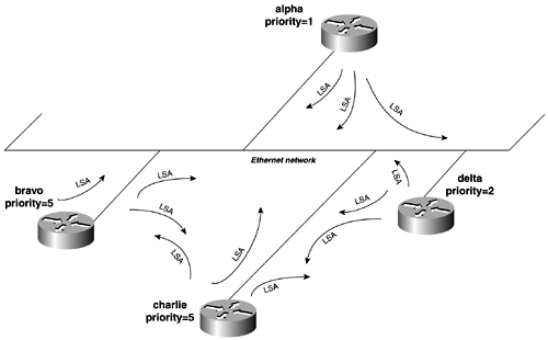
Essentially, the election of a DR and a BDR allows OSPF to streamline routing updates through the network. In the Ethernet example in Figure 12-1, you can see how inefficient the routing process would quickly become in a large network. Without the DR/BDR, every router would need to exchange LS information with every other router on the network.

Figure 12-1. OSPF Ethernet Network LS Propagation Without a DR and BDR (Hypothetical)

graphics/12fig01.gif

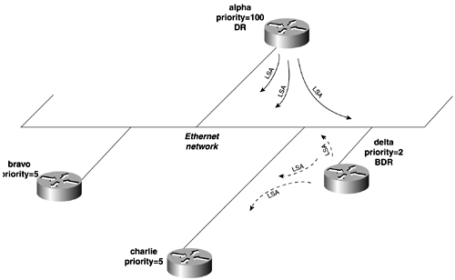
With a DR and BDR in place (see Figure 12-2), LS information, or route information, is controlled by the DR.

Figure 12-2. LS Propagation with a DR and BDR

graphics/12fig02.gif

OSPF Router IDs (RIDs)

The OSPF router ID (RID) is 32-bit unique number assigned to each router running OSPF. This number uniquely identifies the router within the autonomous system. By having a unique router ID for every router within the AS, OSPF can accomplish the following:

  • OSPF easily can identify duplicate LSAs.

  • OSPF is used to identify the unique end points of virtual links.

  • OSPF is used to determine the tie-breaker for DR and BDR negotiations, as mentioned previously.

The router ID is chosen among the interfaces configured for IP on the Cisco router. The router chooses the highest IP address from any operational IP interface. That is, the line is up and the line protocol is up for that interface. If a loopback address is configured on the router, the router chooses that address. If multiple loopback interfaces are configured, it chooses the loopback interface with the highest IP address.

To force a router ID, use a loopback interface with a high IP address, such as 192.168.200.X. It is not necessary to propagate this network in a routing protocol. The networks ”or, more specifically , the IP host addresses used for router IDs ”do not need to be reachable or " ping -able" addresses. In Cisco IOS Software Version 12.0 and above, the OSPF router ID can be hard-coded with the OSPF router command:

 Router(config-router)#  router-id   ip_address  

TIP

It is highly recommended to set the router ID with r outer-id command or by using loopback interfaces. This can greatly increase OSPF network stability. For example, OSPF virtual links rely on the router ID. If the router ID is not fixed and a new network or loopback interface is added to that router, the router ID would be recalculated upon a failure of that router. This could then lead to a change in routers IDs, making the virtual link fail.


The Basic OSPF Adjacency

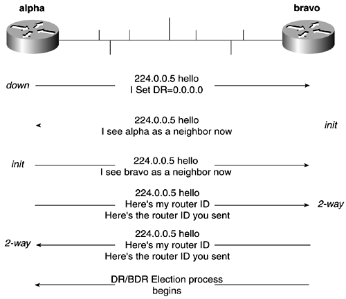
OSPF neighbors go through states before they can begin exchanging LSAs, as illustrated in Figure 12-3. These states are referred to as the neighbor state machine. You can examine the state of an OSPF neighbor with the show ip ospf neighbor command.

Figure 12-3. A Basic OSPF Adjacency

graphics/12fig03.gif

The following list briefly describes the OSPF neighbor states and how they operate :

  • Down ” This is the initial state of the neighbor, which also indicates that no hellos were heard from this neighbor within the last dead time interval.

  • Attempt ” This state applies only to neighbors on NBMA networks, where the neighbors statically are configured with the neighbor command. When the interface becomes active, it goes to the ATTEMPT state, or when the router is DR or BDR.

  • Init ” A hello packet has been received from the neighbor, but two-way communication hasn't taken place yet.

  • 2-way ” This state indicates that a router has seen its own router ID in the Neighbor field of the Hello packet that it received from the neighbor. It also means that bidirectional conversation was established and that DR and BDR election can occur.

When an OSPF interface first becomes active, it begins to send hello packets. When two routers receive each other's hello, they place the neighbor in init status. When a neighbor is in init status, it places its own router ID into the hello packet. When a router receives one of the new hellos with the router ID of its neighbor, it places the neighbor in a new state of 2-way. The 2-way state ensures that there is two-way communication between the routers. The routers must be in this state before they can negotiate a DR/BDR and exchange LSAs.

After the routers have achieved the 2-way state, OSPF enters its final states:

  • ExStart ” The router enters a master/slave relationship and prepares for the exchange of database description packets. The neighbor with the highest interface address becomes the master.

  • Exchange ” The router sends its database description packets to neighbors in the exchange state. The database description packets describe the entire link-state database. The link-state database is synchronized after this phase. After synchronization, the router enters one of two final states:

    - Loading ” The router also sends link-state request packets to all neighbors that are in the loading state. The loading phase requests that more recent LSAs be sent.

    - Full ” Neighbors in this state are fully adjacent.

In summary, the OSPF adjacency is built in four phases:

  1. Neighbors are discovered.

  2. Bidirectional communication is established between neighbors.

  3. The SPF database is synchronized.

  4. Full adjacency is formed.

You can view the status of an OSPF adjacency with the show ip ospf neighbor command, and you can observe the actual building of the adjacency with the debug ip ospf adj command. These and other OSPF status commands are discussed more in upcoming sections.

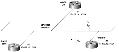
In Figure 12-4, the charlie router is added to an existing OSPF network. By enabling the debug command, you can observe the adjacency being built, as demonstrated in Example 12-1.

Figure 12-4. A Basic OSPF Adjacency Demonstration

graphics/12fig04.gif

Example 12-1 debug ip ospf adj Command Followed by a show ip ospf neighbor Command Demonstrating an Adjacency Forming
 charlie#  debug ip ospf adj  OSPF adjacency events debugging is on OSPF: Interface Ethernet0 going Up OSPF: Build router LSA for area 0, router ID 172.16.1.1 OSPF: Build router LSA for area 0, router ID 172.16.1.1 OSPF: Build router LSA for area 0, router ID 172.16.1.1 %SYS-5-CONFIG_I: Configured from console by console  OSPF: 2 Way Communication to 172.16.1.10 on Ethernet0, state 2WAY graphics/u2192.gif Router enters   two-way state  OSPF: Build router LSA for area 0, router ID 172.16.1.1 OSPF: 2 Way Communication to 172.16.1.5 on Ethernet0, state 2WAY OSPF: Backup seen Event before WAIT timer on Ethernet0  OSPF: DR/BDR election on Ethernet0 graphics/u2192.gif DR/BDR election begins  OSPF: Elect BDR 172.16.1.5 OSPF: Elect DR 172.16.1.10        DR: 172.16.1.10 (Id)   BDR: 172.16.1.5 (Id) OSPF: Send DBD to 172.16.1.5 on Ethernet0 seq 0x1370 opt 0x2 flag 0x7 len 32 OSPF: Send DBD to 172.16.1.10 on Ethernet0 seq 0x218C opt 0x2 flag 0x7 len 32 OSPF: Build router LSA for area 0, router ID 172.16.1.1 OSPF: Rcv DBD from 172.16.1.10 on Ethernet0 seq 0x1137 opt 0x2 flag 0x7 len 32  state EXSTART graphics/u2192.gif EXSTART state begins slave/master will be selected  OSPF: NBR Negotiation Done. We are the SLAVE OSPF: Send DBD to 172.16.1.10 on Ethernet0 seq 0x1137 opt 0x2 flag 0x2 len 52 OSPF: Rcv DBD from 172.16.1.5 on Ethernet0 seq 0x16D9 opt 0x42 flag 0x7 len 32  state EXSTART graphics/u2192.gif EXSTART state begins for the other neighbor  OSPF: NBR Negotiation Done. We are the SLAVE OSPF: Send DBD to 172.16.1.5 on Ethernet0 seq 0x16D9 opt 0x2 flag 0x2 len 52 OSPF: Rcv DBD from 172.16.1.10 on Ethernet0 seq 0x1138 opt 0x2 flag 0x3 len 92  state EXCHANGE graphics/u2192.gif Exchange state begins for one neighbor  OSPF: Send DBD to 172.16.1.10 on Ethernet0 seq 0x1138 opt 0x2 flag 0x0 len 32 OSPF: Database request to 172.16.1.10 OSPF: sent LS REQ packet to 172.16.1.10, length 36 OSPF: Rcv DBD from 172.16.1.5 on Ethernet0 seq 0x16DA opt 0x42 flag 0x3 len 92  state EXCHANGE graphics/u2192.gif Exchange state begins for the other neighbor  OSPF: Send DBD to 172.16.1.5 on Ethernet0 seq 0x16DA opt 0x2 flag 0x0 len 32 OSPF: Database request to 172.16.1.5 OSPF: sent LS REQ packet to 172.16.1.5, length 36 OSPF: Rcv DBD from 172.16.1.10 on Ethernet0 seq 0x1139 opt 0x2 flag 0x1 len 32 s tate EXCHANGE OSPF: Exchange Done with 172.16.1.10 on Ethernet0 OSPF: Send DBD to 172.16.1.10 on Ethernet0 seq 0x1139 opt 0x2 flag 0x0 len 32  OSPF: Synchronized with 172.16.1.10 on Ethernet0, state FULL graphics/u2192.gif LS database is   synced and the adjacency is in FULL status for this neighbor  OSPF: Build router LSA for area 0, router ID 172.16.1.1 OSPF: Rcv DBD from 172.16.1.5 on Ethernet0 seq 0x16DB opt 0x42 flag 0x1 len 32 s tate EXCHANGE OSPF: Exchange Done with 172.16.1.5 on Ethernet0  OSPF: Synchronized with 172.16.1.5 on Ethernet0, state FULL graphics/u2192.gif The same "FULL"   state is achieved with this neighbor  OSPF: Build router LSA for area 0, router ID 172.16.1.1 OSPF: Send DBD to 172.16.1.5 on Ethernet0 seq 0x16DB opt 0x2 flag 0x0 len 32 OSPF: Build router LSA for area 0, router ID 172.16.1.1 charlie# charlie#  show ip ospf neighbor  Neighbor ID     Pri   State           Dead Time   Address         Interface 172.16.1.5        1   FULL/BDR        00:00:35    172.16.1.5      Ethernet0 172.16.1.10       1   FULL/DR         00:00:30    172.16.1.10     Ethernet0 charlie# 

In this example, 172.16.1.10, or the alpha router, became the DR because its IP address is the highest one on the link. The next highest IP address was 172.16.1.5, or the bravo router, so it was elected as the BDR.

Shortest-Path Tree (SPF) and the OSPF Metric Cost

When the LS database is synchronized within an area, the Dijkstra algorithm is run against it in two passes to form the shortest-path (SPF) tree. The first pass against the SPF database forms the branches, or router adjacencies within the area. The second pass adds all leaves or stub networks to the tree. When OSPF builds the tree, it determines the shortest path to each destination based on the sum cost to the destination. The lower the cost is, the more preferred the route is. The cost of a route is the sum of all costs of outgoing interfaces to that destination. Oddly enough, RFC 2328 offers no specific values for cost. Nortel Networks, for example, implements OSPF under RFC 2328 and uses the same formula to generate cost as Cisco Systems. In multivendor environments, take the extra time to see how cost is calculated because it will help OSPF have a consistent view of the entire internetwork.

Cisco routers calculate OSPF cost as (10 8 /BW) rounded down, where BW is the configured or default bandwidth of the interface. Table 12-1 lists the common default OSPF cost settings.

Table 12-1. Default OSPF Interface Cost
Interface Type Default Cost (10 8 /BW)
FDDI, ATM, Fast Ethernet, Gigabit Ethernet (> 100 Mbps) 1
HSSI (45 Mps) 2
16-Mbps Token Ring 6
10-Mbps Ethernet 10
4-Mbps Token Ring 25
T1 (1.544 Mbps) 64
DS-0 (64 kbps) 1562
56 kbps 1785
Tunnel (9 kbps) 11111

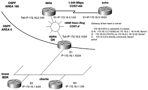
The default cost values can be overridden with the ip ospf cost 1-65535 interface command. The cost for a route can be viewed with the show ip route command. Recall that the variable behind the administrative distance is the metric cost for the router. Figure 12-5 shows a quick example of how cost is calculated. The route table of the echo router lists the cost for network 172.16.2.0 to be 70. The bandwidth of the T1 plus the 16-MB Token Ring equals 70; 64 + 6 = 70. The route to the Ethernet network has a cost of 80; 64 + 6 + 10.

Figure 12-5. OSPF Cost Calculation

graphics/12fig05.gif

OSPF Router Types, Areas, and LSAs

At the onset, we mentioned that OSPF could be considered to be CPU- intensive and difficult to configure. By now, it becomes evident that multiple SPF databases, complex algorithms, and constant CPU interrupts caused by link-state flooding can cause an increase in the router's processor utilization.

To control the flooding of link states and database synchronization, OSPF deploys the use of areas. An OSPF area can be defined as a group of routers and links that divide an OSPF domain into subdomains. Areas are identified by a 32-bit area ID, which then also can be expressed in dotted -decimal notation or as a decimal number.

There are five types of areas in OSPF:

  • Backbone area or Area 0 (or 0.0.0.0) ” All traffic must pass through the backbone area; nonbackbone areas do not exchange packets directly. All areas also must be adjacent to Area 0. The backbone must be continuous and cannot be partitioned. Area 0 can be extended by the use of a virtual link.

  • Nonbackbone, nonstub area ” This is a normal OSPF area other than Area 0. All LSAs, except Type 7, are flooded into this area.

  • Stub area ” No external routes are advertised into a stub area, nor will they generate external LSA type 5s. A backbone area will advertise a single default route to a stub area or a network summary LSA for the destination 0.0.0.0. Some other restrictions on stub areas apply:

    - Virtual links cannot be configured across stub areas.

    - Adjacencies will not be established with any other router not configured as a stub, except for the Area Border Router.

    - No router within a stub area can be an ASBR because no external routes or LSA Type 5 can be advertised out of a stub area. In short, stub areas cannot perform redistribution.

    - LSA Types 4 and 5 are blocked into the area. Only LSA Types 1, 2, and 3 are flooded into the area.

  • Totally stubby area ” Neither external nor internal routes are advertised into this area. LSA types 3, 4, and 5 are blocked into the area, except for a single default route advertised as a LSA type 3. The router will use the default route to reach any destination outside the area.

  • Not-so-stubby area (NSSAs) ” Sometimes, it is necessary to redistribute another routing protocol, such as RIP, into a stub area. Because this violates the definition of stub area, a new area type was needed. To remedy this, RFC 1587 defines not-so-stubby areas (NSSA). An NSSA allows external routes to be advertised into the OSPF domain while retaining the other characteristics of a stub area. When external routes are redistributed into a router in an NSSA area, the router originates LSA Type 7s to advertise the new external destination(s) to routers within the NSSA area. The LSA Type 7s are converted to LSA Type 5 when flooded into Area 0 by the ABR. No LSA type 5s will exist in the NSSA area. All routers in the area must be configured NSSA.

OSPF requires a hierarchical network design through the use of areas controlled by specific router types. A router might be multiple router types; for example, ABRs are also backbone routers. The OSPF router types are as follows :

  • Internal routers ” Internal routers are routers whose interfaces all reside in the same OSPF area. All internal routers have the same SPF database.

  • Area Border Routers (ABRs) ” ABRs are routers that connect one or more areas to the backbone area. They forward all LSAs from the backbone area. The ABR always has at least one interface in Area 0 and keeps a separate SPF database for each area that it is connected to. These should be high-end routers for this reason.

  • Backbone routers ” These are routers that have at least one interface in Area 0. All interfaces might reside in Area 0, in which case the router is an internal backbone router.

  • Autonomous System Boundary Routers(ASBRs) ” Routers that redistribute another routing protocol or advertise external routes are called ASBRs.

The word LSA has been mentioned quite a bit. LSAs are what OSPF uses to build the OSPF database. OSPF floods specific LSA types to specific portions of the OSPF domain as dictated by the area and router type mentioned previously. LSA are classified by type, and each type serves a specific purpose, as described in the following list:

  • Router LSA (Type 1) ” This LSA contains information about a router and the links that it has in an area. LSA type 1s are flooded only in that area. The LSA also tells whether the router is a stub or ASBR, or whether it has one end of a virtual link. OSPF represents these routes in the forwarding table with an O.

  • Network LSA (Type 2) ” This LSA is used for transit networks within an area. It describes the set of routers attached to a network. LSA Type 2s are not flooded outside an area. OSPF represents these routes in the forwarding table with an O.

  • Summary LSAs for ABRs (Type 3) ” These LSAs advertise internal networks to routers in other areas, called OSPF interarea routes. The LSA might contain a summary network or a single network. ABRs are the only router type that generates this LSA type. OSPF represents these routes in the forwarding table with an O IA.

  • Summary LSA for ASBRs (Type 4) ” These LSAs are used to advertise the location of an ASBR. Routers searching for a path to an external network use LSA Type 4 to determine the best next hop. OSPF represents these routes in the forwarding table with an O IA. This LSA type is hard to remember, so you can think of it as the "how do I get out here LSA."

  • Autonomous system external LSAs (Type 5) ” Type 5 LSAs are used to advertise routes redistributed into OSPF. These routes are called OSPF external routes, and they are flooded throughout the entire OSPF autonomous system, except for stub, totally stubby, and NSSA areas. OSPF represents these routes in the forwarding table with an O E1 or O E2, depending on the route.

  • NSSA external LSA (Type 7) ” This type of LSA is generated for the external routes redistributed into a not-so-stubby area. They are flooded throughout the NSSA area. When they hit an ABR, the ABR advertises them as Type 5 LSAs into Area 0. Type 7 LSAs never leave the NSSA area. OSPF represents these routes in the forwarding table with an O N1 or O N2, depending on how the route was redistributed.

Table 12-2 summarizes the LSAs that are allowed in each area.

Table 12-2. LSA Types Allowed in Each Area
Area Type LSA 1 and 2 LSA 3 and 4 LSA 5 LSA 7
Backbone area (Area 0) Yes Yes Yes No
Stub area Yes Yes No No
Totally stubby area Yes No [*] No No
Not-so-stubby area Yes Yes No Yes
Nonbackbone, nonstub area Yes Yes Yes No

[*] One LSA Type 3 is used to advertise the default route

NOTE

RFC 2370 defines opaque link states. Opaque LSAs are Type 9, 10, and 11 link-state advertisements. These advertisements might be used directly by OSPF or indirectly by some application wanting to distribute information throughout the OSPF domain, such as RSVP. The function of the opaque LSA option is to provide for future extensibility of OSPF. The following section is taken directly from RFC 2370:

3.0 The Opaque LSA

Opaque LSAs are types 9, 10 and 11 link-state advertisements. Opaque LSAs consist of a standard LSA header followed by a 32-bit aligned application-specific information field. Standard link-state database flooding mechanisms are used for distribution of Opaque LSAs. The range of topological distribution (i.e., the flooding scope) of an Opaque LSA is identified by its link-state type. This section documents the flooding of Opaque LSAs.

The flooding scope associated with each Opaque link-state type is defined as follows.

Link-state type 9 denotes a link-local scope. Type-9 Opaque LSAs are not flooded beyond the local (sub)network.

Link-state type 10 denotes an area-local scope. Type-10 Opaque LSAs are not flooded beyond the borders of their associated area.

Link-state type 11 denotes that the LSA is flooded throughout the Autonomous System (AS). The flooding scope of type-11 LSAs are equivalent to the flooding scope of AS-external (type-5) LSAs. Specifically type-11 Opaque LSAs are 1) flooded throughout all transit areas, 2) not flooded into stub areas from the backbone and 3) not originated by routers into their connected stub areas. As with type-5 LSAs, if a type-11 Opaque LSA is received in a stub area from a neighboring router within the stub area the LSA is rejected.


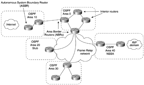
Figure 12-6 illustrates a modern OSPF network, highlighting the different router types.

Figure 12-6. OSPF Network Router types

graphics/12fig06.gif

OSPF Acknowledgments

To ensure that LSAs are transmitted successfully, OSPF requires each LSA to be acknowledged. LSAs are acknowledged by one of the following acknowledgment types:

  • Implicit acknowledgment ” Occurs when the sending router receives a duplicate LSA from the neighbor. By seeing the neighbor report the LSA, the router knows "implicitly" that it received the LSA.

  • Explicit acknowldgment ” Requires the receiving router(s) to send a specific link-state acknowledgement packet in response to the LSA.

To ensure that LSAs are current and valid, each LSA has a sequence number, a checksum, and a MaxAge value. The sequence number and checksum verify that the LSA is valid, whereas the age parameter ensures that the LSA is the most current LSA. MaxAge is used to verify how old the LSA was. MaxAge is set for 3600 seconds, or 1 hour . When a router originates an LSA, it sets the MaxAge at 0. Each time the LSA is flooded by another router, its MaxAge is incremented by another timer called InfTransDelay, which has a default value of 1. When the LSA reaches the MaxAge value, the LSA is reflooded throughout the network. Routers also use the MaxAge parameter when comparing two LSAs to determine which one is more current. This type of flooding can be excessive on large stable networks. In Cisco IOS 12.1, Cisco introduced a concept called LSA flooding reduction. LSA flooding control is discussed more in upcoming sections.

OSPF Path Types

When you perform the show ip route command on OSPF, each route is classified in OSPF as one of six path types. The path is preceded by a tag representing the route's type. The path types and tags used are as follows:

  • (O) Intra-area paths/routes ” These are routes to networks within the same OSPF area.

  • (O IA) Interarea paths/routes ” These are routes to networks in different OSPF areas but within the same OSPF autonomous system.

  • (O E1) External Type 1 paths/routes ” When an external route is redistributed into OSPF, it must be assigned a metric or cost. Type 1 paths have a cost that is the sum of this external path/metric plus the internal cost of the path to the ASBR reporting the route.

  • (O E2) External Type 2 paths/routes ” This is the same as a Type 1 route, except for the fact that the internal cost to the ASBR is not added to the default cost of the path. By default, all routes distributed into OSPF become external Type 2 routes. This can be changed during redistribution.

  • (O N1) OSPF NSSA type 1 ” When an external route is redistributed into an OSPF NSSA area, it becomes this type. Type 1 paths have a cost that is the sum of this external path/metric plus the internal cost of the path to the router reporting the route.

  • (O N2) OSPF NSSA type 2 ” This is the same as a Type 1 route, except that the internal cost to the router is not added to the default cost of the path. By default, all routes distributed into OSPF NSSA area become OSPF NSSA external Type 2 routes. This can be changed during redistribution.

Example 12-2 lists a complex route table with four types of OSPF routes.

Example 12-2 Complex OSPF Route Table
 skynet#  show ip route  Codes: C - connected, S - static, I - IGRP, R - RIP, M - mobile, B - BGP        D - EIGRP, EX - EIGRP external, O - OSPF, IA - OSPF inter area        N1 - OSPF NSSA external type 1, N2 - OSPF NSSA external type 2        E1 - OSPF external type 1, E2 - OSPF external type 2, E - EGP        i - IS-IS, L1 - IS-IS level-1, L2 - IS-IS level-2, * - candidate default        U - per-user static route, o - ODR Gateway of last resort is 172.16.128.1 to network 0.0.0.0      10.0.0.0/24 is subnetted, 1 subnets O       10.10.10.0 is a summary, 03:05:49, Null0      129.201.0.0/24 is subnetted, 1 subnets O E1    129.201.1.0 [110/90] via 172.16.2.66, 03:05:45, TokenRing1      128.200.0.0/24 is subnetted, 1 subnets D EX    128.200.1.0 [170/679936] via 172.16.192.3, 05:42:57, Serial1      129.200.0.0/24 is subnetted, 1 subnets O E1    129.200.1.0 [110/90] via 172.16.2.66, 03:05:45, TokenRing1      128.201.0.0/24 is subnetted, 1 subnets D EX    128.201.1.0 [170/679936] via 172.16.192.3, 05:42:57, Serial1 C    201.201.101.0/24 is directly connected, Loopback0 O E2 132.31.0.0/16 [110/2] via 172.16.2.66, 00:58:04, TokenRing1 O E2 131.31.0.0/16 [110/2] via 172.16.2.66, 00:58:04, TokenRing1      172.16.0.0/16 is variably subnetted, 27 subnets, 4 masks O IA    172.16.152.0/24 [110/71] via 172.16.2.66, 03:05:45, TokenRing1 O IA    172.16.150.0/24 [110/80] via 172.16.2.66, 03:05:45, TokenRing1 O IA    172.16.151.0/24 [110/71] via 172.16.2.66, 03:05:45, TokenRing1 C       172.16.144.0/21 is directly connected, Loopback20 C       172.16.136.0/21 is directly connected, Ethernet1 C       172.16.128.0/21 is directly connected, Ethernet0 C       172.16.220.0/24 is directly connected, Loopback69 C       172.16.192.0/24 is directly connected, Serial1 C       172.16.192.3/32 is directly connected, Serial1 O IA    172.16.42.2/32 [110/70] via 172.16.2.66, 03:05:46, TokenRing1 O IA    172.16.42.3/32 [110/70] via 172.16.2.66, 03:05:46, TokenRing1 O E2    172.16.42.0/24 [110/2] via 172.16.2.66, 03:05:46, TokenRing1 O IA    172.16.42.1/32 [110/6] via 172.16.2.66, 03:05:46, TokenRing1 O IA    172.16.21.0/24 [110/76] via 172.16.2.66, 03:05:46, TokenRing1 O IA    172.16.22.0/24 [110/71] via 172.16.2.66, 03:05:46, TokenRing1 O E2    172.16.1.0/24 [110/2] via 172.16.2.66, 03:05:46, TokenRing1 O E2    172.16.2.0/24 [110/2] via 172.16.2.66, 03:05:46, TokenRing1 D       172.16.102.0/24 [90/679936] via 172.16.192.3, 05:42:59, Serial1 D       172.16.103.0/24 [90/409600] via 172.16.128.1, 05:42:59, Ethernet0 O E2    172.16.84.0/24 [110/2] via 172.16.2.66, 03:05:47, TokenRing1 O E2    172.16.85.0/24 [110/2] via 172.16.2.66, 03:05:47, TokenRing1 O E2    172.16.81.0/24 [110/2] via 172.16.2.66, 03:05:47, TokenRing1 O E2    172.16.82.0/24 [110/2] via 172.16.2.66, 03:05:47, TokenRing1 O E2    172.16.83.0/24 [110/2] via 172.16.2.66, 03:05:47, TokenRing1 O E2    172.16.64.0/24 [110/2] via 172.16.2.66, 03:05:47, TokenRing1 <<<text omitted>>> 

This section on the technical aspects of OSPF is meant to give you a solid background on OSPF fundamentals so that the configuration commands will have a firmer meaning when used. Several books have been written on OSPF describing in further detail OSPF packet structure, as well as other OSPF intricacies. For further reading, we suggest Jeff Doyles's Routing TCP/IP , Volume I; Tom Thomas's OSPF Network Design Solutions ; and John Moy's OSPF, Anatomy of an Internet Routing Protocol . The Cisco OSPF design guide on www.cisco.com and RFC 2328 also make good references.

 <  Free Open Study  >  


CCIE Practical Studies, Volume I
ISBN: 1587200023
EAN: 2147483647
Year: 2001
Pages: 283
Authors: Karl Solie

flylib.com © 2008-2017.
If you may any questions please contact us: flylib@qtcs.net