Tuning EIGRP Updates
| < Free Open Study > |
Tuning, Redistribution, and Controlling IGRP UpdatesLike RIP, IGRP has several parameters for tuning timers, controlling broadcasts, load-sharing, and controlling routes. The following is a list of parameters adjustable within IGRP:
The following subsets of commands are used to influence routing decisions. Individual metrics can be modified, as can the administrative distance of the IGRP. Whenever influencing a specific links metric, use the delay command over the bandwidth command. Both can be used, but OSPF also is affected by bandwidth, whereas delay affects only IGRP and EIGRP.
Unequal -Cost Load BalancingIGRP has the capability to use unequal-cost load balancing. The router uses variance as a multiplier in choosing the upper boundary of path with the greatest metric. Configuring unequal-cost load balancing is a three-step process:
The following example walks through the calculation of a fictional variance. IGRP has a route, and the metric of that route is 100. The router also has two more routes to that same destination, and the metrics for those routes are 200 and 300. To allow IGRP to use all three paths in sharing data, you would set the variance to 3. (3 x 100) = 300, or (Best_metric) x (variance) = Largest metric of path to load share over. To properly set the variance, use the following formula: The metric of the lowest-cost route can be discovered with the debug ip igrp transactions command. Be sure to change the variance and other variables on both ends of the link. The bandwidth also should be set on all serial links. The following syntax is used in configuring load balancing:
For a route to be included in unequal-cost load sharing, three other conditions must be met:
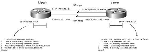
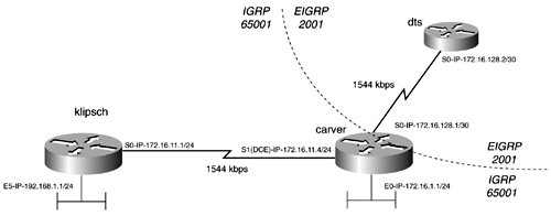
Configuring IGRP Unequal-Cost Load SharingIn the network model in Figure 10-2, there are two routers: klipsch and carver. The routers are connected by two serial links: One link is running at 56 kbps, and the other is running at T1 speeds. The routers are both running IGRP in the private autonomous system of 65,001. In this model, you want to enable unequal-cost load balancing across the serial links. Figure 10-2. IGRP with Unequal Metric Calculation The first step, after configuring basic IGRP, is to set the bandwidth on the serial interfaces. If IGRP is enabled without tuning the bandwidth, the routers get an inconsistent view of the metrics of the network. In Example 10-6, the klipsch router has calculated a composite metric of 180,671 for the subnet 172.16.1.0 from the Serial 1 interface. On the other hand, the router has calculated a metric of 8576 for the same route from the Serial 0 interface. How IGRP calculates the metrics for each route can be displayed by the debug ip igrp transactions command, as shown in Example 10-6. Example 10-6 Metric of the 172.16.1.0 Route on klipschklipsch# debug ip igrp transactions IGRP protocol debugging is on klipsch# 00:50:05: IGRP: received update from 172.16.11.4 on Serial0 00:50:05: subnet 172.16.10.0, metric 182571 (neighbor 180571) 00:50:05: subnet 172.16.1.0, metric 8576 (neighbor 1100) 00:50:05: IGRP: received update from 172.16.10.4 on Serial1 00:50:05: subnet 172.16.11.0, metric 182571 (neighbor 8476) 00:50:05: subnet 172.16.1.0, metric 180671 (neighbor 1100) 00:50:05: subnet 172.16.100.0, metric 182671 (neighbor 8576) klipsch# Example 10-7 illustrates how, without setting the bandwidth on both sides of the serial links, the routers might have different perspectives on the link. Example 10-7 Metric of 192.168.1.0 Route of carvercarver# debug ip igrp transactions IGRP protocol debugging is on 03:12:26: IGRP: received update from 172.16.11.1 on Serial1 03:12:26: subnet 172.16.10.0, metric 10476 (neighbor 8476) 03:12:26: network 192.168.1.0, metric 8576 (neighbor 1100) 03:12:26: IGRP: received update from 172.16.10.1 on Serial7 03:12:26: subnet 172.16.11.0, metric 90956 (neighbor 8476) 03:12:26: network 192.168.1.0, metric 89056 (neighbor 1100) carver# To assist in synchronizing the metrics, assign the bandwidth statement to the two serial interfaces. Once again, this is done with the bandwidth kbps interface command. After applying the bandwidth command, the metrics are consistent throughout the network, as shown in Example 10-8. Example 10-8 debug ip igrp transactions Command Output on the klipsch and carver Routersklipsch# 03:54:18: IGRP: received update from 172.16.11.4 on Serial0 03:54:18: subnet 172.16.10.0, metric 182571 (neighbor 180571) 03:54:18: subnet 172.16.1.0, metric 8576 (neighbor 1100) 03:54:19: IGRP: received update from 172.16.10.4 on Serial1 03:54:19: subnet 172.16.11.0, metric 182571 (neighbor 8476) 03:54:19: subnet 172.16.1.0, metric 180671 (neighbor 1100) 03:54:19: network 192.168.1.0, metric 182671 (neighbor 8576) ______________________________________________________________ carver# 03:49:31: IGRP: received update from 172.16.11.1 on Serial1 03:49:31: subnet 172.16.10.0, metric 182571 (neighbor 180571) 03:49:31: network 192.168.1.0, metric 8576 (neighbor 1100) 03:49:31: IGRP: received update from 172.16.10.1 on Serial7 03:49:31: subnet 172.16.11.0, metric 182571 (neighbor 8476) 03:49:31: subnet 172.16.1.0, metric 182671 (neighbor 8576) 03:49:31: network 192.168.1.0, metric 180671 (neighbor 1100) carver# carver# The routing table is now consistent and all traffic flows through the lowest-cost path. Notice in Figure 10-3 that the routing table for the klipsch router now reports only the lowest-cost path to the network 172.16.1.0. Figure 10-3. IGRP with Equal Metric Calculation The final step is to set the variance. Recall that the formula to calculate variance is as follows : Therefore, in this example, you have 1 + (180671/8576) = 22. After the variance is set, the router reports two paths to the destination network and load-share over them. The load sharing is in an inverse proportion to the variance setting. In this model, every 22nd packet crosses the lowest-cost path. Finally, Example 10-9 lists the route table on the carver and klipsch routers when unequal-cost load balancing is in effect. Notice that all possible paths to the destination networks are listed. Example 10-9 show ip route Command Output Lists All Possible Paths to Remote NetworksI 192.168.1.0/24 [100/8576] via 172.16.11.1, 00:01:09, Serial1 [100/180671] via 172.16.10.1, 00:01:10, Serial7 172.16.0.0/24 is subnetted, 3 subnets C 172.16.10.0 is directly connected, Serial7 C 172.16.11.0 is directly connected, Serial1 C 172.16.1.0 is directly connected, Ethernet0 carver# ______________________________________________________________ 172.16.0.0/24 is subnetted, 3 subnets C 172.16.10.0 is directly connected, Serial1 C 172.16.11.0 is directly connected, Serial0 I 172.16.1.0 [100/8576] via 172.16.11.4, 00:00:20, Serial0 [100/180671] via 172.16.10.4, 00:00:20, Serial1 C 192.168.1.0/24 is directly connected, Ethernet5 klipsch# Example 10-10 lists the configuration of the carver and klipsch routers. Example 10-10 Relevant Portions of the carver and klipsch Router Configurationshostname carver ! interface Ethernet0 ip address 172.16.1.1 255.255.255.0 ! interface Serial1 ip address 172.16.11.4 255.255.255.0 bandwidth 1544 clockrate 2000000 ! interface Serial7 ip address 172.16.10.4 255.255.255.0 bandwidth 56 clockrate 56000 ! router igrp 65001 variance 22 network 172.16.0.0 ! ip classless ______________________________________________________________ hostname klipsch ! interface Ethernet5 ip address 192.168.1.1 255.255.255.0 media-type 10BaseT ! interface Serial0 ip address 172.16.11.1 255.255.255.0 no ip mroute-cache bandwidth 1544 ! interface Serial1 ip address 172.16.10.1 255.255.255.0 bandwidth 56 ! router igrp 65001 variance 22 network 172.16.0.0 network 192.168.1.0 ! ip classless IGRP and EIGRP Integration and MigrationMigration from IGRP to EIGRP was designed to be an effortless migration. For the most part, this is true. If IGRP and EIGRP use the same Autonomous System IDs, redistribution occurs automatically. This facilitates a rather painless migration from IGRP to EIGRP. If the routing processes are in different autonomous systems, manual redistribution must be configured. IGRP is also a classful routing protocol, which means that routing updates in the same major class or bit boundary as the interface receiving the update must have a subnet mask that matches the mask of the interface receiving the update. If the update is in a different class, it automatically is summarized at that class's major bit boundary, 8-bit, 16-bit, or 24-bit. Therefore, care must be taken to use summarization so that all the networks are at the same bit boundary throughout the portion of the network that supports only classful routing. Expanding upon the model from the previous example, a new router has been added to the internetwork and some other subnet changes have been made, as illustrated in Figure 10-4. There now exists an EIGRP domain in the model. A router called dts is connected by a T1 serial link to the carver router. Figure 10-4. IGRP and EIGRP Integration To integrate the dts router to the network, manual redistribution is necessary. This is because the network resides in different autonomous systems. Example 10-11 highlights the IGRP and EIGRP redistribution on the carver router. The passive-interface commands are not necessary but are configured to prevent unnecessary EIGRP hellos and IGRP broadcast from entering networks that they shouldn't. Example 10-11 IGRP and EIGRP Redistribution on the carver Router! router eigrp 2001 redistribute igrp 65001 The link between the carver and dts routers is on a 30-bit boundary. IGRP is not capable of advertising this network after it is redistributed because the subnet mask does not match the subnet mask on the advertising interface. To remedy this, summarize the 172.16.128.0/30 network to 172.16.128.0/24 by using the ip summary-address eigrp 2001 172.16.128.0 255.255.255.0 command under the Serial 0 interface of the carver router. Downstream routers, such as klipsch, now have IP reachability to the subnet 172.16.128.0/24. Example 10-12 lists the route table of the klipsch router. Example 10-12 Route Table of the klipsch Router klipsch# show ip route <<<text omitted>>> Gateway of last resort is not set 172.16.0.0/24 is subnetted, 3 subnets I 172.16.128.0 [100/10476] via 172.16.11.4, 00:00:31, Serial0 C 172.16.11.0 is directly connected, Serial0 I 172.16.1.0 [100/8576] via 172.16.11.4, 00:00:31, Serial0 klipsch# IGRP and Default RoutingA default route is necessary whenever connecting to the Internet because, without it, the router would need a path to every single network in its routing table. Fundamentally, a default route points to a gateway of last resort. When a router cannot find a specific match in its route table for a packet, it forwards that packet to the gateway of last resort. Cisco routers always perform a classful route lookup, which means that they do not forward packets to a gateway of last resort unless the global ip classless command is set. ip classless is enabled by default in Cisco IOS Software Release 11.3 and later. The concept of default routing varies by each routing protocol. Each routing protocol uses a specific method when defining and advertising a default route. The two steps to perform when configuring default routing with IGRP follow:
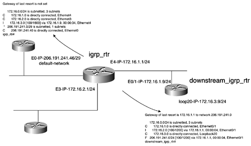
In Figure 10-5, igrp_rtr has a default network of 206.191.241.40/29. The ip default-network 206.191.241.0 command has been added to the configuration. This causes the route to be flagged as a default and as an external network. The route table for the igrp_rtr router marks this route with an *, meaning that the route is the candidate default. When the route is propagated to a downstream router, it becomes a gateway of last resort, as shown in Figure 10-5. Figure 10-5. IGRP Default Network Example 10-13 lists the configuration of the igrp_rtr router. Example 10-13 Relevant Portions of the igrp_rtr Configurationrouter igrp 2001 network 172.16.0.0 network 206.191.241.0 ! ip classless ip default-network 206.191.241.0 ! |
| < Free Open Study > |
EAN: 2147483647
Pages: 283


