Configuring IGRP
| < Free Open Study > |
Technical Overview of RIPRFC 1058 outlines RIP-1, and RFCs 1721, 1722, and 1723 are supplemental RFCs that allow for RIP-2 extensions. NOTE You can find all RFCs online at http://www.isi.edu/in-notes/rfcxxxx.txt, where xxxx is the number of the RFC. RIP operates on UDP port 520 ”that is, all RIP packets have a source and destination port equal to 520. RIP operates in the following manner:
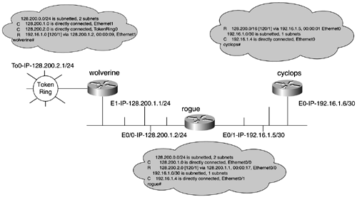
All the timers can be changed with the timers basic update invalid holddown flush command. CAUTION When adjusting the timers for RIP, all the timers in the routing domain must also be adjusted. Failure to do so can cause many unpredictable results. Classful Routing (RIP-1 Only)RIP-1 is a classful routing protocol, so it does not advertise a subnet mask along with advertised routes. For RIP to determine what the subnet mask is of the destination network, RIP uses the subnet mask of the interface in which the route was received. This is true only if the route received is a member of a directly connected major network. If the route received is not of the same major network, the router tries to match only the major bit boundary of the route ”either Class A, B, or C. For this reason, it is critical to preserve a consistent bit mask in each major network throughout the entire RIP routing domain. Figure 9-1 illustrates classful routing on a RIP-1 network. Let's examine how the wolverine and rogue routers handle the RIP process. Figure 9-1. Classful Routing Example The wolverine router has two interfaces in the 128.200.0.0 major network. The 24-bit mask is consistent on every interface on the router. Therefore, the router receives updates only for the major network 128.200.0.0 on the 24-bit boundary. When the router receives the update out of this major network ”for example, 192.16.1.4/30 ”it enters only a summary route in its routing table pointing to the major bit or class boundary of the address, summarizing the address to 192.16.1.0/24. Example 9-1 shows the output of debug ip rip demonstrating this concept. Example 9-1 debug ip rip Command Output on wolverine01:24:39: RIP: sending v1 update to 255.255.255.255 via Ethernet1 (128.200.1.1) 01:24:39: subnet 128.200.2.0, metric 1 01:24:39: RIP: Update contains 1 routes 01:24:39: RIP: Update queued 01:24:39: RIP: Update sent via Ethernet1 01:24:39: RIP: sending v1 update to 255.255.255.255 via TokenRing0 (128.200.2.1) 01:24:39: subnet 128.200.1.0, metric 1 01:24:39: network 192.16.1.0, metric 2 01:24:39: RIP: Update contains 2 routes 01:24:39: RIP: Update queued 01:24:39: RIP: Update sent via TokenRing0 The rogue router has two interfaces. One is in the 128.200.0.0/16 major network, and the other is in the 192.16.1.0/24 network. When the rogue router receives the 128.200.2.0/24 and 128.200.1.0/24 subnets from its E0/0 interface, it tries to send them out its E0/1 interface. Because this interface has a different mask (30-bit), only the summary route 128.200.0.0/16 is sent to the cyclops router. Example 9-2 demonstrates this happening, through the aid of debug ip rip. Example 9-2 debug ip rip Command Output on rogueRIP: received v1 update from 128.200.1.1 on Ethernet0/0 128.200.2.0 in 1 hops RIP: sending v1 update to 255.255.255.255 via Ethernet0/0 (128.200.1.2) network 192.16.1.0, metric 1 RIP: sending v1 update to 255.255.255.255 via Ethernet0/1 (192.16.1.5) network 128.200.0.0, metric 1 Classless Routing (RIP-2 Only)RIP-2 is not a new routing protocol, but it is an extension of RIP-1 provided by RFCs 1721, 1722, and 1723. The extensions provide the following enhancements to RIP:
The most significant of all the enhancements is the support for VLSM, making RIP-2 a classless routing protocol. It is no longer critical to have one bit mask throughout the entire routing domain. Most of RIP-2 operational procedures and timers are identical to those of RIP-1. RIP-2 uses the multicast address of 224.0.0.9 to send updates versus the general all- hosts broadcast used by RIP-1. RIP-2 is fully backward compatible with RIP-1. This is accomplished by the means of a compatibility switch and a receive control switch, as defined in RFC 1723. Essentially, these switches allow you to control what type of RIP updates the router sends and receives. The router can be configured to receive only Version 1 updates, only Version 2 updates, both, or none. The router can send only Version 1 updates, send Version 2 updates as a broadcast message, send Version 2 updates as a multicast, or send no updates. The switches can be manually set with the following interface command: ip rip [ send receive ] version [ 1 2 1 2 ] |
| < Free Open Study > |
EAN: 2147483647
Pages: 283
