Planning for Fault Tolerance
|
Fault tolerance is the ability to encounter failures and still continue to function. Fault tolerance is created by using a combination of redundancy (the duplication of components or resources), efficient distribution of workload, proper planning, proper procedures, and training. When all of these are done correctly and in the right proportions, high availability is the result.
To properly plan for fault tolerance, examine all of the possible areas a failure could occur that would affect continuous operation. The following are the most common areas of failure:
-
Hardware (disk, RAM, CPU, power supply, cooling fans, and network)
-
Infrastructure (power feeds, environmental, and wide-area communications)
-
Operational (documentation, change of media, and procedures)
-
Functional (placing too many critical processes into a failure-susceptible area).
One fault-tolerant-related phrase you may have heard before is five nines, which is a reference to the larger scale of nines measure of computer system availability first developed by Jim Gray. The scale of nines refers to the percentage of downtime allowed per year, described by the number of nines in the availability statistic. Five nines refers to an achievable level of reliability in the middle scale. Table 8.2 illustrates the amount of downtime each level of “nines” means per year.
| Name | Percentage of Uptime per Year | Effective Downtime per Year |
|---|---|---|
| One nine | 90% | 36 days, 12 hours |
| Two nines | 99% | 3 days, 15 hours, 36 minutes |
| Three nines | 99.9% | 8 hours, 45 minutes, 36 seconds |
| Four nines | 99.99% | 52 minutes, 34 seconds |
| Five nines | 99.999% | 5 minutes, 15 seconds |
| Six nines | 99.9999% | 31.5 seconds |
| Seven nines | 99.99999% | 3.2 seconds |
| Eight nines | 99.999999% | 0.32 second |
| Nine nines | 99.9999999% | 0.03 second |
Five nines reliability is commonly discussed because it is possible to achieve given current technology. The primary factor with the scale of nines is cost. Higher levels of availability are becoming possible to achieve, but they usually come at a steep price.
Network Fault-Tolerance Solutions
One area of component failure is the network interface. If a system has one interface to a network, and a component of that interface fails (the switch, the cable, or the NIC), the whole interface fails. As a result, it is a good idea to build redundancy into your network interfaces.
Several manufacturers sell NICs that have two or more ports. Using the appropriate drivers, these cards usually support either a failover configuration or a load-balanced configuration, which work as follows:
-
Failover Keeps one port idle and waiting, while the other port(s) handle communications. If a component of that interface fails, the idle port comes online and takes over for the failed port. A failover configuration can be used with switches or nonswitched network hubs.
-
Load-balanced configuration Uses multiple ports simultaneously and spreads the communication load among the ports. In the event of an interface failure, the communications load is reassigned to the remaining active ports. A load-balanced configuration yields higher availability and performance but can be used only in conjunction with higher-end intelligent switches.
Some network topology issues can affect network availability as well. When designing a network, keep in mind all of the potential failure points, including routers, switches, bridges, and wide area network (WAN) components.
In all but the smallest networks, it is a good idea to have redundant functionality for critical services. If you are using AD, make sure that you have more than one domain controller and DNS server. If you are using WINS, create a secondary WINS server and have it replicate with the primary WINS server. If you are using DHCP, create a secondary DHCP server on each subnet and configure each with the appropriate scopes. Following these guidelines will ensure continued operation of these services in the event of failures.
Internet Fault-Tolerance Solutions
Many of the Internet fault-tolerance solutions are the same as general network fault-tolerance solutions, but there are a few extra considerations. Network Load Balancing (NLB) is a set of features included with all versions of Windows Server 2003 that can increase the redundancy, performance, and availability of Web sites. NLB allows multiple Windows Server 2003 Web servers to share and distribute the load of serving Web pages and other network-based applications. NLB is discussed in Chapter 9.
Most medium and large networks access the Internet through a proxy server. A proxy server is a server that accesses the Internet on behalf of a requesting client, caches the results, and then passes the requested pages back to the client. Subsequent requests are then served from cache, and actual traffic to the Internet is reduced. This can increase the performance for clients when accessing Web pages. Some proxy servers also add security and other features. If your environment includes a proxy server, consider building redundancy into it. A secondary proxy server may be in order.
The actual communication circuits and Internet Service Providers (ISPs) are other potential points of failure. It is common for large companies and organizations to have multiple WAN circuits and even multiple circuits to more than one ISP. This increases cost but also reduces the likelihood of a communications failure usually outside your control.
Disk Fault-Tolerance Solutions
The most common hardware component that fails is the hard drive. Even though modern disk drives commonly operate for months or years without incident, failure is a given. As a result, disk fault-tolerance solutions are some of the most well-developed and reliable technologies, and they employ some of the oldest and simplest techniques. It is not uncommon to see other areas of technology borrow concepts that were first seen in the development of disk fault tolerance.
The disk controller is the first component to consider. Although the controller itself is generally considered more reliable than the disk drive, a controller can (depending on the technology in use) support multiple drives. This can make the failure of a controller have a stronger impact than if a single drive fails. A configuration that uses multiple controllers connected to a set of drives is often called duplexing. Multiple controllers increase the cost and complexity of the configuration, but they can help to eliminate the controller as a point of failure.
RAID
Redundant drives are more common than redundant controllers. Using a technique called RAID, data is duplicated on multiple drives, prevents the failure of any single drive from causing downtime. Like many fault-tolerant solutions, RAID can also have a performance impact. RAID can be done via specialized hardware controllers or via software. Hardware solutions are generally faster and more portable; software solutions are cheaper.
A group of RAID-configured drives is called a drive array or simply an array. The structure of an array is usually described as its level. A level refers to a specific type or combination of redundancy in use. There are several defined RAID levels. The most common RAID levels are described in the following sections.
RAID 0
RAID 0 (also called striping) provides increased read and write performance and does not provide redundancy. Data is split into smaller uniform-sized blocks (or stripes), as illustrated in Figure 8.63, and is written to read from multiple drives at the same time. Multiple drives with smaller blocks of data increase the performance, but the failure of any drive destroys all data. The level is used mainly for ultra high-performance databases. RAID 0 requires a minimum of two drives, although more are commonly used. The maximum number of drives allowed using a Windows Server 2003 striped volume is 32.
RAID 1
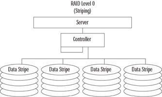
Figure 8.63: RAID 0
RAID 1 (also called mirroring) provides redundancy by duplicating the exact contents of one drive onto another, as illustrated in Figure 8.64. If one drive fails, the other has a complete copy of the data. This is a very reliable method of protecting data. It has a small write performance impact, because data must be written twice (once to each drive). It also has a read impact, because often information can be read from either or both drives at the same time.
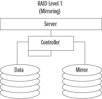
Figure 8.64: RAID 1
A variation of this RAID level called duplexing uses a controller for each mirrored disk, as illustrated in Figure 8.65. Duplexing can improve performance while increasing fault tolerance. RAID 1 is considered expensive because one half of the total disk space is used for providing redundancy. This level is commonly used for high-value, moderate performance data like log files.
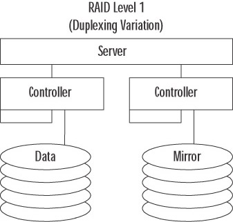
Figure 8.65: RAID 1 Duplexing Variation
RAID 5
RAID 5 (also called striping with parity) is perhaps the most common level of RAID 5. As shown in Figure 8.66, this level combines the concept of parity with the technique of striping. Parity is a mathematical value that can be used to re-create missing data. When using Windows Server 2003 software-based RAID 5, a minimum of three drives is required and a maximum of 32 are allowed. When a block of data is written to disk, it is split into smaller, uniform-sized blocks. An additional block of data (the parity block) is created from a mathematical calculation based on the other blocks of data. Finally, all the blocks of data are written in a stripe to the disks. If a drive fails, the original data can be re-created by doing the reverse of the parity calculation. RAID 5 exacts a performance impact for writes (the parity calculation) but yields a performance increase on reads (from striping). RAID 5 is commonly used to provide redundancy at a lower effective cost than RAID 1.
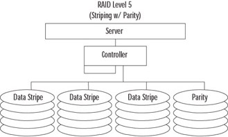
Figure 8.66: RAID 5
RAID 0+1
RAID 0+1 (also called mirroring plus striping), as its name implies, combines the performance and redundancy benefits of RAID levels 0 and 1. As shown in Figure 8.67, each disk in a RAID 0+1 array is mirrored, preventing the failure of any single drive (and sometime multiple drive failures) from causing downtime. In addition, each drive in a RAID 0+1 array receives only a portion of the total data load, yielding a tremendous performance increase. RAID 0+1 is the most expensive and complex RAID configuration, but it is also the highest performing. RAID 0+1 is used where the value of the data is high, the performance demand is high, and the cost considerations are secondary. Databases commonly reside on RAID 0+1 arrays.
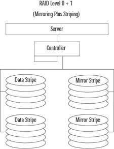
Figure 8.67: RAID 0+1
Hot Spare Drives
Another important feature to consider is the use of hot spare drives. Most modern, fault-tolerant disk controllers support the use of additional hard drives that wait for an existing drive in an array to fail. When the controller determines that a drive has failed, it activates the hot spare drive and uses it to replace the failed drive in the array. The data that was present on the failed drive is re-created on the hot spare drive by the fault-tolerant controller, not Windows. In this way, an array may operate for a brief time in a decreased availability state, but will not require attention from an administrator to recover from that state.
Server Fault-Tolerance Solutions
The server is our final point of consideration for fault-tolerance. Our focus in this section is on the server system itself, not on the workload or the services it provides. There are two basic methods for introducing fault-tolerance on a server: hardware redundancy and virtualization (called clustering).
Modern server hardware is designed around increasing performance and reliability. Higher-end (more complicated and expensive) servers often include many built-in redundancy features. It is possible to find servers that support spare RAM and CPUs, redundant power supplies and cooling fans, built-in hardware RAID support, and many other features integrated into the basic system. In addition, many components in modern higher-end servers are hot-swappable, meaning the power does not need to be turned off in order to remove or change the component.
Another hardware component that is often overlooked but is easily acquired and implemented is a redundant power source. Ideally, you want duplicate power sources all the way back to duplicate utility companies, but that is usually not possible. What is possible is the installation of an Uninterruptible Power Supply (UPS) and the software to communicate with it. A UPS is basically a large battery, although this term is sometimes also used to refer to a generator. Your equipment plugs into the UPS, and the UPS plugs into utility power. If utility power is cut, the UPS continues to power your equipment. Most often, a UPS is used to provide power long enough for a proper system shutdown. Size a UPS by the amount of power it must provide and the length of time needed to run when on battery. The more equipment on a UPS or the longer the required runtime, the “larger” the UPS must be. In very large environments, consider multiple UPSs operating in parallel (never “daisy-chain” UPSs) and possibly a backup generator.
| Exam Warning | In addition to your servers, you may also need to have your switches and hubs, a monitor, and other equipment plugged into a UPS. Many UPS systems come with software that uses the network to notify servers that power has been lost. If the network hardware does not have power, servers will not receive these messages. As a result, they will not know they need to shut down. In addition, you may want to leave hardware plugged in that allows you to interact with the server during power outages. That will be hard to do without a monitor. |
Server virtualization refers to a method used to reduce the dependence of the services provided by a server on the hardware it runs on. Server clusters are used for this purpose. Server clusters are discussed in Chapter 9.
|
EAN: 2147483647
Pages: 173