Allowing Outbound Traffic
|
Once the initial configuration of the PIX firewall is complete, the first step to passing traffic is to configure the PIX to allow outbound access. Outbound connections on the PIX are defined as connections from a higher security-level interface to a lower security-level interface. Allowing outbound traffic to traverse the PIX requires either configuring address translation or explicitly disabling it. Once address translation is configured, by default, if no access lists or apply/outbound statements are applied, all outbound traffic is allowed. This is a primary feature of the Adaptive Security Algorithm (ASA) and is the reason why security levels are so critical. Since the PIX is stateful, when an outbound connection is initiated, traffic returning to that connection is allowed to traverse back from the lower security-level interface to the higher security-level interface.
Configuring Dynamic Address Translation
Configuring address translation is the first step to pass outbound traffic. Address translation (through NAT and/or PAT) is used to map local IP addresses to global IP addresses. Once NAT and/or PAT are configured, the ASA automatically allows traffic to traverse from a higher security-level interface to a lower security-level interface on the PIX firewall (also known as outbound connections). The ASA also permits any return traffic related to these outbound connections.
Configuration of NAT/PAT is a two-step process:
-
Use the nat command to identify the local addresses that will be translated.
-
Use the global command to define the global addresses to translate to.
On the PIX firewall, address translation records are known as translation slots (or xlate) and are stored in a table known as the translation table. To view the contents of this table, use the show xlate command. The xlate timer monitors the translation table and removes records that have been idle longer than the defined timeout. By default, this timeout is set to three hours, and the current settings can be verified by using the show timeout command. The syntax of the nat command is as follows:
nat [(<if_name>)] <id> <local_address> [<netmask> [outside] [dns] [norandomseq] [timeout <hh:mm:ss>] [<connection_limit> [<embryonic_limit>]]
The if_name parameter is used to apply the nat command to the interface where the traffic to be translated enters the PIX. This parameter must match the name used to describe an interface with the nameif command. If this parameter is not specified, the inside interface is assumed.
The id parameter is an integer between 0 and 2,000,000,000 that is used to establish a mapping between the local IP addresses (local_address) identified by the nat command and the global IP addresses specified by the global command. The id 0 is special and is used to specify that you do not want the specified local addresses translated. In other words, the local addresses and the global addresses will be the same.
The netmask parameter is used with local_address to be more specific about the IP addresses to translate. The outside keyword allows for external addresses to be translated. The dns keyword configures the PIX to translate the IP address included in DNS responses using active entries in the translation table. By default, when performing address translation, the PIX firewall also randomizes the sequence numbers in TCP segments. The norandomseq keyword tells the PIX not to randomize the sequence numbers. This is useful when you will be performing address translation twice (for example, when you have two PIX firewalls in the path) and do not require the sequence numbers to be randomized twice. The timeout parameter defines how long to allow an entry in the translation table to stay idle.
The connection_limit parameter defines how many total concurrent active connections are allowed, and the embryonic_limit parameter defines how many concurrent half-open connections are allowed. Both of these parameters default to 0, which indicates unlimited connections. Too many half-open connections can result from a DoS attack, and tuning the embryonic_limit parameter can help reduce the impact of these attacks.
The syntax for the global command is as follows:
global [(<if_name>)] <id> { {<global_ip> [-<global_ip>] [netmask <global_mask>]} | interface} The if_name parameter defines the interface on which traffic will exit after being translated. If the if_name parameter is not specified, the outside interface is assumed. The id parameter matches one or more nat statements to a global statement. The global_ip parameter defines the global IP addresses to be used in translation. If a single IP address is specified, port address translation is performed. If a range is specified, network address translation is used until no more global addresses are available. Once all global addresses have been exhausted, port address translation is performed. The netmask keyword is associated with the global_ip range, so the PIX will not use broadcast or network addresses in its translation. If the global IP address to be used is assigned to an interface, the interface keyword can be used to instead of global_ip to specify this.
Let's look at an example of Secure Corporation, a company that has decided to wire three buildings in London and provide Internet access to its employees. This company does not own any Internet address space. One of the company's requirements is to use private address space, because it does not want to readdress the entire network if it has to change ISPs. By using a private IP address scheme, the company can change public IP addresses whenever circumstances require, and all it will have to do is associate the new IP address range to the private IP addresses. Figure 9.1 shows the network layout. (Note: Even though it is a private address range, the 10.0.0.0/8 network is being used to represent the public IP address space in this chapter. Keep this in mind as you read the rest of the chapter.)
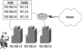
Figure 9.1: A Network Address Translation Example
In Figure 9.1, you can see that each of the three buildings has been assigned a 24-bit network from a range specified in RFC1918. These ranges are 192.168.1.0/24, 192.168.2.0/24, and 192.168.3.0/24, respectively. Each ISP-assigned 24-bit subnet (10.1.1.0/24, 10.1.2.0/24, and 10.1.3.0/24) has been mapped to a private address range. This configuration allows each node to have a unique public IP address dynamically mapped from a pool associated with the originating building. This setup allows the system administrators to track down employees very quickly. The configuration in this example is fairly straightforward. Traffic to be translated must be identified using the nat command and then mapped to a pool of public IP addresses defined by the global command. The commands to configure this are as follows:
PIX1(config)# nat (inside) 1 192.168.1.0 255.255.255.0 PIX1(config)# global 1 10.1.1.1-10.1.1.254 netmask 255.255.255.0 PIX1(config)# nat (inside) 2 192.168.2.0 255.255.255.0 PIX1(config)# global 2 10.1.2.1-10.1.2.254 netmask 255.255.255.0 PIX1(config)# nat (inside) 3 192.168.3.0 255.255.255.0 PIX1(config)# global 3 10.1.3.1-10.1.3.254 netmask 255.255.255.0 PIX1(config)# exit PIX1# clear xlate
| Note | The clear xlate command is used to clear contents in the translation table. This command should be executed after any translation configuration changes are made; otherwise, there is a danger of stale entries sticking around in the translation table. |
To make sure that everything was typed in correctly, use the show nat and show global _commands:
PIX1# show nat nat (inside) 1 192.168.1.0 255.255.255.0 0 0 nat (inside) 2 192.168.1.0 255.255.255.0 0 0 nat (inside) 3 192.168.1.0 255.255.255.0 0 0 PIX1# show global global (outside) 1 10.1.1.1-10.1.1.254 netmask 255.255.255.0 global (outside) 2 10.1.2.1-10.1.2.254 netmask 255.255.255.0 global (outside) 3 10.1.3.1-10.1.3.254 netmask 255.255.255.0
In the example we just discussed, the ISP provided enough public addresses that Secure Corp. was able to create a one-to-one mapping between local and global addresses. What would happen if the ISP did not allocate enough public address space? Let's assume that the ISP provided a single 24-bit public address range (10.1.1.0/24). Instead of using separate global pools, the company could use one global pool for all buildings and use PAT. PAT allows many IP addresses to be translated to fewer IP addresses by translating both the IP address and the source port. The configuration would be as follows:
PIX1(config)# nat (inside) 1 192.168.1.0 255.255.255.0 PIX1(config)# nat (inside) 1 192.168.2.0 255.255.255.0 PIX1(config)# nat (inside) 1 192.168.3.0 255.255.255.0 PIX1(config)# global (outside) 1 10.1.1.1-10.1.1.254 netmask 255.255.255.0 PIX1(config)# exit PIX1# clear xlate
| Note | PAT works with DNS, FTP, HTTP, mail, RPC, RSH, Telnet, URL filtering, and outbound traceroute. PAT does not work with H.323, caching name servers, and PPTP. |
To enable NAT to work on multiple interfaces, separate global commands are needed for each interface to translate to. The key is making sure you use the same id on all the global commands. Doing so allows one set of nat commands on the inside interface to translate a private IP address to one of many different global address ranges based on destination. For example, the following commands would configure the PIX to NAT the 192.168.1.0/24 network to either a 10.1.1.0/24 address or PAT to the DMZ interface IP address, depending on the interface the packet was going to exit:
PIX1(config)# nat (inside) 1 192.168.1.0 255.255.255.0 PIX1(config)# global (outside) 1 10.1.1.1-10.1.1.254 netmask 255.255.255.0 PIX1(config)# global (dmz) 1 interface PIX1(config)# exit PIX1# clear xlate
As with most commands on the PIX firewall, use the no keyword with the nat and global commands to remove them from the configuration.
Identity NAT and NAT Bypass
Using our Secure Corp. example, consider that instead of using private IP addresses inside the PIX, the company decided to use public IP addresses. Secure Corp. has been assigned a block of portable IP space from the American Registry for Internet Numbers (ARIN) in the form of three 24-bit networks. The corporation chooses, as shown in Figure 9.2, not to use private addressing within its network.
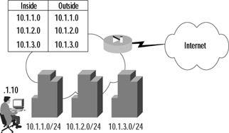
Figure 9.2: An Identity Network Address Translation Example
Looking at Figure 9.2, you can see that each of the three ARIN-assigned 24-bit subnets has been allocated to a building. In this example, public addresses will be used both inside and outside the PIX firewall, and no address translation will be performed. There are two ways to accomplish this task: using identity NAT or using NAT bypass.
In identity NAT, instead of using an associated global command to define the global address, the internal address is mapped to itself when translating. To configure identity NAT, use the nat command with an id of 0, and do not define an associated global command. The commands to configure the PIX in Figure 9.2 would be as follows:
PIX1(config)# nat (inside) 0 10.1.1.0 255.255.255.0 nat 0 10.1.1.0 will be non-translated PIX1(config)# nat (inside) 0 10.1.2.0 255.255.255.0 nat 0 10.1.2.0 will be non-translated PIX1(config)# nat (inside) 0 10.1.3.0 255.255.255.0 nat 0 10.1.3.0 will be non-translated PIX1(config)# exit PIX1# clear xlate
To verify the configuration, use the show nat command to view the current NAT configuration:
PIX1# show nat nat (inside) 0 10.1.1.0 255.255.255.0 0 0 nat (inside) 0 10.1.2.0 255.255.255.0 0 0 nat (inside) 0 10.1.3.0 255.255.255.0 0 0
Let's examine the example in Figure 9.2. The client opens a connection to a Web server on the Internet. Since the ASA defines that, by default, higher security-level interfaces can send traffic to lower security-level interfaces, the traffic should traverse the PIX and be listed in the xlate table. The show xlate debug command should show a mapping for this connection, and it should be flagged with an I, or identity flag.
PIX1# show xlate debug 1 in use, 1 most used Flags: D - DNS, d - dump, I - identity, i - inside, n - no random, o - outside, r - portmap, s - static NAT from inside:10.1.1.10 to outside:10.1.1.10 flags iI idle 0:01:27 timeout 3:00:00
The other way to configure the PIX to keep local and global addresses the same is to bypass NAT altogether using nat 0 with an access list. First, you must define an access list that identifies the traffic to be translated (access lists are discussed in detail in the next section). Then, use the nat command with an id of 0 and the access list name to bypass the NAT process. The syntax to configure this is:
access-list <acl_name> permit ip <source_addr> <source_mask> <dest_addr> <dest_mask> nat (<if_name>) 0 access-list <acl_name>
Using Figure 9.1 as an example, the commands to configure the PIX to bypass NAT using an access list would be as follows:
PIX1(config)# access-list inside_public permit ip 10.1.1.0 255.255.255.0 any PIX1(config)# access-list inside_public permit ip 10.1.2.0 255.255.255.0 any PIX1(config)# access-list inside_public permit ip 10.1.3.0 255.255.255.0 any PIX1(config)# nat (inside) 0 access-list inside_public PIX1(config)# exit PIX1# clear xlate
To verify the configuration, use the show nat and show access-list commands:
PIX1# show nat nat (inside) 0 access-list inside_public PIX1# show access-list access-list inside_public; 3 elements access-list inside_public permit ip 10.1.1.0 255.255.255.0 any (hitcnt=0) access-list inside_public permit ip 10.1.2.0 255.255.255.0 any (hitcnt=0) access-list inside_public permit ip 10.1.3.0 255.255.255.0 any (hitcnt=0)
Returning to our example in Figure 9.2, when the client opens a connection to a Web server on the Internet, the show xlate debug command should not show a mapping for this connection since it bypasses NAT. Instead, the show access-list command should show an incremented hitcnt counter on the appropriate access list entry.
PIX1# show xlate 0 in use, 1 most used PIX1# show access-list inside_public access-list inside_public; 3 elements access-list inside_public permit ip 10.1.1.0 255.255.255.0 any (hitcnt=10) access-list inside_public permit ip 10.1.2.0 255.255.255.0 any (hitcnt=0) access-list inside_public permit ip 10.1.3.0 255.255.255.0 any (hitcnt=0)
Although identity NAT and NAT bypass provide similar functionality, using NAT bypass provides some advantages over identity NAT. These advantages include saving resources by bypassing the NAT process as well as allowing for greater flexibility in configuration by including the option to specify destination addresses in the access list.
Blocking Outbound Traffic
As discussed previously, without any configuration the PIX ASA allows all higher security-level interfaces to send traffic to lower security-level interfaces. If certain outbound traffic needs to be blocked, this must be done explicitly. Although the practice is not required, controlling the outbound traffic that is allowed to traverse the PIX firewall is always a part of a well-designed security policy. There are two ways to accomplish this task: using access lists or using outbound/apply statements. Access lists, introduced in PIX firewall software v5.0, are the newer and recommended method for controlling outbound access on the PIX firewall. Only use outbound/apply statements if you have to (for example, if you have an older version of the PIX software).
Access Lists
Access lists on the PIX firewall are very similar to those used on Cisco routers and can be used to limit the traffic allowed to traverse the PIX based on several criteria, including source address, destination address, source TCP/UDP ports, and destination TCP/UDP ports. Access list configuration is a two-step process:
-
The access list itself is defined by creating permit and deny statements using the access-list command.
-
The access list is applied to an interface using the access-group command.
There are two different syntaxes for the access-list command. The first is used for any protocol other than Internet Control Message Protocol (ICMP), and the second is used for ICMP:
access-list <acl_name> {deny | permit} <protocol> <src_addr> <src_mask> [<dest_operator> <dest_port>] <dest_addr> <dest_mask> [<dest_operator> <dest_port>] access-list <acl_name> {deny | permit} icmp <src_addr> <src_mask> <dest_addr> <dest_mask> <icmp_type> The acl_name parameter is the name of an access list and can be either a name or a number. The permit and deny keywords are self-explanatory. The protocol parameter specifies the IP protocol. You can either enter the numerical value or specify a literal name. Possible literal names are listed in Table 9.1.
| Literal | Value | Description |
|---|---|---|
| ah | 51 | Authentication header for IPv6, RFC 1826 |
| eigrp | 88 | Enhanced Interior Gateway Routing Protocol |
| esp | 50 | Encapsulated Security Payload for IPv6, RFC 1827 |
| gre | 47 | General Routing Encapsulation |
| icmp | 1 | Internet Control Message Protocol, RFC 792 |
| igmp | 2 | Internet Group Management Protocol, RFC 1112 |
| igrp | 9 | Interior Gateway Routing Protocol |
| ip | 0 | Internet Protocol |
| ipinip | 4 | IP-in-IP encapsulation |
| nos | 94 | Network Operating System (Novell's NetWare) |
| ospf | 89 | Open Shortest Path First routing protocol, RFC 1247 |
| pcp | 108 | Payload Compression Protocol |
| snp | 109 | Sitara Networks Protocol |
| tcp | 6 | Transmission Control Protocol, RFC 793 |
| udp | 17 | User Datagram Protocol, RFC 768 |
The address of the network or host from which the packet originated is specified using the src_addr parameter. The src_mask parameter specifies the netmask bits to apply to src_addr. To specify all networks or hosts, use the any keyword, which is equivalent to a source network and mask of 0.0.0.0 0.0.0.0. Use the host keyword followed by an IP address to specify a single host. The dest_addr and dest_mask are similar to the src_addr and src_mask parameters, except that they apply to destination addresses.
| Note | The syntax for access lists on the PIX firewall is very similar to that of Cisco routers. The key difference is that access lists on PIX firewalls use standard wildcard masks, whereas on routers they use inverse wildcard masks. For example, when blocking a 24-bit subnet, you would use a mask of 255.255.255.0 on a PIX firewall and a mask of 0.0.0.255 on a Cisco router. |
An operator comparison lets you specify a port or port range and is used in combination with the tcp or udp protocol keywords. To specify all ports, do not specify an operator and port. Use eq to specify a single port. Use gt to specify all ports greater than the specified port. Use neq to specify all ports except a given number. Finally, use range to define a specific range of ports. The port can be specified using either a number or a literal name. A list of literal port names is presented in Table 9.2.
| Name | Port | Protocol | Name | Port | Protocol | Name | Port | Protocol |
|---|---|---|---|---|---|---|---|---|
| bgp | 179 | tcp | http | 80 | tcp | radius | 1645, 1646 | udp |
| biff | 512 | udp | hostname | 101 | tcp | rip | 520 | udp |
| bootpc | 68 | udp | ident | 113 | tcp | smtp | 25 | tcp |
| bootps | 67 | udp | irc | 194 | tcp | snmp | 161 | udp |
| chargen | 19 | tcp | isakmp | 500 | udp | snmptrap | 162 | udp |
| citrix-ica | 1494 | tcp | klogin | 543 | tcp | sqlnet | 1521 | tcp |
| cmd | 514 | tcp | kshell | 544 | tcp | sunrpc | 111 | tcp/udp |
| daytime | 13 | tcp | login | 513 | tcp | syslog | 514 | udp |
| discard | 9 | tcp/udp | lpd | 515 | tcp | tacacs | 49 | tcp/udp |
| dnsix | 195 | udp | mobile-ip | 434 | udp | talk | 517 | tcp/udp |
| domain | 53 | tcp/udp | nameserver | 42 | udp | telnet | 23 | tcp |
| echo | 7 | tcp/udp | netbios-dgm | 138 | udp | tftp | 69 | udp |
| exec | 512 | tcp | netbios-ns | 137 | udp | time | 37 | udp |
| finger | 79 | tcp | nntp | 119 | tcp | uucp | 540 | tcp |
| ftp | 21 | tcp | ntp | 123 | udp | who | 513 | udp |
| ftp-data | 20 | tcp | pim-auto-rp | 496 | tcp/udp | whois | 43 | tcp |
| gopher | 70 | tcp | pop2 | 109 | tcp | www | 80 | tcp |
| h323 | 1720 | tcp | pop3 | 110 | tcp | xdmcp | 177 | tcp |
Note that the system-defined port mapping of http is the same as www and is silently translated in the configuration. The icmp_type parameter allows you to permit or deny access to ICMP message types. A list of ICMP message types can be found in Table 9.3.
| ICMP Type | Literal |
|---|---|
| 0 | echo-reply |
| 3 | unreachable |
| 4 | source-quench |
| 5 | redirect |
| 6 | alternate-address |
| 8 | echo |
| 9 | router-advertisement |
| 10 | router-solicitation |
| 11 | time-exceeded |
| 12 | parameter-problem |
| 13 | timestamp-reply |
| 14 | timestamp-request |
| 15 | information-request |
| 16 | information-reply |
| 17 | mask-request |
| 18 | mask-reply |
| 31 | conversion-error |
| 32 | mobile-redirect |
After configuring an access list, you must apply it to an interface using the following command:
access-group <acl_name> in interface <if_name>
The name associated with an access list is specified as acl_name, whereas the name of the interface that the access list will use to monitor inbound traffic is specified by if_name. An access list, once applied to an interface using the access-group command, denies or permits traffic as it enters the PIX on the specified interface.
| Note | Access lists on the PIX firewall can only be applied to traffic entering an interface, not traffic that is exiting an interface. This is unlike Cisco routers, on which access lists can be applied in either direction. |
Access lists on the PIX firewall have an implicit deny all attached to the end of the access list. This means that unless traffic has been specifically permitted within the access list, it will be denied by a phantom entry that follows the last entry in every access list. This feature helps ensure that security will be maintained even in the face of configuration errors. Coupling this feature with the fact that access lists are processed sequentially from the first entry to the last, a PIX administrator can create very complex access lists simply by following the flow of what should and should not be allowed. Only one access list at a time can be applied to an interface.
Let's now look at an example of Secure Corp., which has just purchased a new PIX firewall for its network in New York, as shown in Figure 9.3. All the servers that the company hosts at the site, as well as all the clients within the network, are located on the inside interface of the PIX. The site uses a single network with the address space of 192.168.0.0/22. The ISP has assigned the 10.1.1.0/24 public network to use.
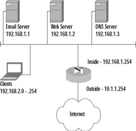
Figure 9.3: The Secure Corporation Access List Example
The company's requirements are that the clients only be able to access the Internet with their Web browsers and that the company servers have unrestricted access to the Internet. The design of an access list should start with a definition of what is going to be allowed and then proceed to what is going to be denied. In this example, the access list will have to allow clients in the 192.168.2.0/24 range to access any Internet server on TCP port 80. Second, the access list will have to allow the three listed servers unfettered access to the Internet. The following commands accomplish this result:
PIX1(config)# access-list inside_in permit tcp 192.168.2.0 255.255.255.0 any eq 80 PIX1(config)# access-list inside_in permit ip 192.168.1.1 255.255.255.255 any PIX1(config)# access-list inside_in permit ip 192.168.1.2 255.255.255.255 any PIX1(config)# access-list inside_in permit ip 192.168.1.3 255.255.255.255 any PIX1(config)# access-group inside_in in interface inside
A good practice is to add an explicit deny all statement to the end of an access list so you remember it is there when you do a show access-list command and so you can see how many packets have been dropped using the hitcnt counter:
PIX1(config)# access-list inside_in deny ip any any PIX1(config)# exit PIX1# show access-list access-list inside_in; 4 elements access-list inside_in permit tcp 192.168.2.0 255.255.255.0 any eq www (hitcnt=2) access-list inside_in permit ip host 192.168.1.1 any (hitcnt=0) access-list inside_in permit ip host 192.168.1.2 any (hitcnt=0) access-list inside_in permit ip host 192.168.1.3 any (hitcnt=0) access-list inside_in deny ip any any (hitcnt=40)
Best security practices dictate that publicly accessible servers should not be located on the inside network; instead, they should be located on a DMZ network. The DMZ provides an extra layer of security and helps control the risks associated with a publicly accessible server. If the server becomes compromised, because it is in a DMZ with separate security settings it is possible to contain the compromise to the DMZ and still protect inside clients. However, if the network is set up as in the previous example and the server becomes compromised, there is very little that can be done to stop that server from compromising the entire internal network. Keeping this design practice in mind, Figure 9.4 shows a revised network layout.
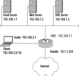
Figure 9.4: Secure Corporation Revised Network Layout
From the diagram, it is apparent that the network requirements have changed, because services the clients used to be able to get to without going through the firewall now need to be added to the access lists. Unlike the access list created before, the servers should not be allowed to access any IP address without restriction. A DMZ access list should be created that locks down the services that the servers are able to use, because if these servers become compromised, you want to limit their ability to infect your network or even someone else's. The commands to create and apply these access lists are:
PIX1(config)# access-list inside_in permit tcp 192.168.2.0 255.255.255.0 any eq www PIX1(config)# access-list inside_in permit tcp 192.168.2.0 255.255.255.0 192.168.1.1 eq smtp PIX1(config)# access-list inside_in permit tcp 192.168.2.0 255.255.255.0 192.168.1.1 eq pop3 PIX1(config)# access-list inside_in permit udp 192.168.2.0 255.255.255.0 192.168.1.3 eq domain PIX1(config)# access-list inside_in permit tcp 192.168.2.0 255.255.255.0 192.168.1.3 eq domain PIX1(config)# access-list inside_in deny ip any any PIX1(config)# access-group inside_in in interface inside PIX1(config)# access-list dmz_in permit tcp 192.168.1.1 255.255.255.255 any eq smtp PIX1(config)# access-list dmz_in permit udp 192.168.1.3 255.255.255.255 any eq domain PIX1(config)# access-list dmz_in permit tcp 192.168.1.3 255.255.255.255 any eq domain PIX1(config)# access-list dmz_in deny ip any any PIX1(config)# access-group dmz_in in interface dmz
It is important to note that we have not yet covered how to configure inbound access. The preceding access list only allows these servers to initiate contact with other servers—as a client would do. For example, the e-mail server can send mail to another domain, but it cannot receive it. The DNS server can resolve domain information from another domain, but it cannot respond to queries from other domains. The "Allowing Inbound Traffic" section of this chapter covers in detail how inbound access is enabled.
One very useful feature in configuring the PIX is the name command. This command allows you to define a name alias to an IP address so that during configuration, instead of referencing a host by its IP address, the host can be referenced by a name. This feature is very useful for configuring complex configurations, because a descriptive name can be very helpful in configuring and troubleshooting the PIX configuration. The syntax for the command is:
name <ip_address> <name>
For example, the following command maps the name mail to the IP address 10.1.1.10:
PIX1(config)# name 10.1.1.10 mail
The name mail can now be used in access lists instead of an IP address.
Outbound/Apply
The outbound and apply commands can also be used to control which traffic is allowed to exit the network. The outbound command by itself only identifies traffic to be permitted or denied. The apply command applies the outbound list to an interface and actually causes packets to be dropped. The first step to controlling outbound traffic is to configure the outbound command to identify the traffic to be filtered. The syntax for the outbound command is:
outbound <list_id> permit | deny <ip_address> [<netmask> [<port>[-<port>]] [<protocol>]
The list_id is an identifier that maps the traffic identified by the outbound command to the apply command; list_id must be a number between 1 and 99. The permit or deny keywords specify whether the traffic identified by the outbound command will be permitted or denied, respectively. The ip_address parameter specifies the traffic to be identified by the outbound command. The netmask parameter is used in conjunction with the ip_address parameter to identify traffic from an entire network. The port parameter specifies a specific port number or range to be identified by the outbound command. The protocol parameter specifies a specific protocol to be identified (tcp, udp, etc.) and is assumed to be ip if it is not specified.
The second step to controlling outbound traffic is to apply the outbound list to an interface using the apply command. Once the apply command is committed to an interface, any incoming traffic to that interface that is denied by the associated outbound list will be dropped. The syntax for the apply command is as follows:
apply [(<if_name>)] <list_id> outgoing_src | outgoing_dest
The interface_name parameter specifies the interface on which traffic will be filtered using the associated outbound list, and if not specified is assumed to be the outside interface. The list_id parameter associates the outbound list to use to filter outbound traffic. Unlike access lists, multiple outbound lists can be applied to an interface, and the lists are processed starting at the lowest number and working toward the highest.
The outgoing_src or outgoing_dest keywords are parameters that define how the apply command uses the associated outbound list to filter traffic. If outgoing_src is used, the ip_address parameter in the outbound list is a source address. If outgoing_dest is used, the ip_address parameter in the outbound list is a destination address.
Secure Corp. has decided to implement access restrictions from its networks to the Internet. To control what employees can access, the company systems administrators decide to deny all packets sourced from within the company destined to echo, chargen, and discard ports on the Internet. They choose these ports because they are common ports for attacking Internet servers and there is no reason why an employee should need access to these services on an outside host.
To accomplish this task, it will be helpful to create an outbound list. The first step to configure this list is to allow all traffic through. The next step is defining the rules that deny access to the specific services. Finally, the outbound list needs to be applied to an interface. The commands to do these tasks are as follows:
PIX1(config)# outbound 20 permit 0.0.0.0 0.0.0.0 0 PIX1(config)# outbound 20 deny 0.0.0.0 0.0.0.0 echo PIX1(config)# outbound 20 deny 0.0.0.0 0.0.0.0 discard PIX1(config)# outbound 20 deny 0.0.0.0 0.0.0.0 chargen PIX1(config)# apply (inside) 20 outgoing_src
Unfortunately, even after taking all the precautions we've described, the company gets a phone call that someone in the company is attempting to access a server on the Internet that he should not. The IP address of the Internet server that is being attacked is 10.10.1.10. Therefore, a new outbound rule needs to be created. Since the company has yet to figure out who is causing the trouble, instead of identifying traffic on the source address, administrators need to use the apply command to match on the destination:
PIX1(config)# outbound 30 permit 0.0.0.0 0.0.0.0 0 PIX1(config)# outbound 30 deny 10.10.1.10 255.255.255.255 0 PIX1(config)# apply (inside) 30 outgoing_dest
Another way to accomplish this task is to use the outbound command with the except keyword. The except keyword causes the normal behavior of the outbound list to be exactly opposite for the specified IP address. For example, if the normal behavior of a rule is to allow all source addresses to access all services, an except parameter would make a specific destination be denied. Therefore, in the preceding example, instead of creating a new outbound list, we could add an except parameter to outbound list 20:
PIX1(config)# outbound 20 except 10.10.1.10 255.255.255.255 0
To verify your configuration, use the show outbound [list_id] command.
| Note | It might be desirable to block Java applets or ActiveX code coming in from the Internet. The PIX supports this functionality. |
|
EAN: 2147483647
Pages: 240