PIX Firewall Features
|
The PIX 500 series firewalls are a market-leading security appliance, and for good reason. They provide robust performance in a firewall while providing a highly scalable architecture ranging from plug-and-play SOHO devices to carrier-class firewalls with gigabit connections. They provide protective services that define what a firewall should do. From stateful packet inspection to content filtering, VPN termination to address translation, support for PKI applications, and providing security to multimedia applications, the PIX does it all.
With such flexibility comes the requirement to configure the devices correctly. Luckily, for those who are already comfortable with a router prompt, the PIX is based on a familiar command prompt. Of course, the PIX fits into standard Cisco management tools such as CiscoWorks, so it will seamlessly integrate into your LAN/WAN environment.
Embedded Operating System
Many firewalls are based on general-purpose operating systems (OSs). This means that maintenance is required to ensure not only correct configuration but that the base OS is patched and secured. This requirement offers both a higher long-term cost as well as the potential for security weaknesses.
An embedded OS is one in which the OS is self-contained in the device and resident in ROM. This involves reduced maintenance costs, since no customizations or OS configurations are required; a single image is downloaded and stored to flash. It means that there is little that can go wrong; you cannot accidentally leave an unnecessary service running, since the firewall has all its services tuned to only those features appropriate for a security device.
Unlike some appliances that are based on a general kernel such as Linux or Windows CE, the PIX is based on a hardened, specialized OS specific to security services. This OS allows for kernel simplification, which supports explicit certification and validation: The PIX OS has been tested for vendor certification such as ICSA Labs' firewall product certification criteria and the very difficult-to-obtain International Standards Organization (ISO) Common Criteria EAL4 certification. This testing allows for maximum assurance in deployment from Cisco's positive security engineering based on good commercial development practices. Kernel simplification has advantages in throughput as well; the PIX 535 will support up to 256,000 simultaneous connections, far exceeding the capabilities of a UNIX- or Windows-based OS on equivalent hardware.
One key advantage to the software on a PIX firewall is its similarity to Cisco IOS. This means that internetworkers have the ability to rapidly master management of the PIX, reducing deployment costs and supporting management by network operations center (NOC) personnel. You should not have to be an expert in UNIX or Windows 2000 to be able to deploy a VPN or firewall!
The Adaptive Security Algorithm
The heart of the PIX is the Adaptive Security Algorithm, or ASA. The ASA is a mechanism to determine if packets should be passed through the firewall, consistent with the information flow control policy as implemented in the access control list (ACL) table. The PIX evaluates packet information against developed state and decides whether to pass the packet.
Let's go through this process one step at a time. First, there is the concept of a datastream. Packets that are flowing across a wire have identifying characteristics: IP address of source and destination, sometimes numbers associated with the type of communication (ports) of source and destination, and numbers such as IP identifiers or synchronization and acknowledgment numbers that identify where a packet belongs in a particular connection. When you open a Web page—say, to www.cisco.com/index.html—you establish a connection between your browser and the Web server. One piece of HTML is transferred; if it has not been cached, this page represents about 90K of text. That text might then open up additional connections for all the embedded pictures. The process involves a "dance" between browser and server—a "handshake" to initialize the connection, a "get" to specify the data being requested, a "response" to say if the data is available, and the actual data itself. Since the file is so large, these steps all occur in multiple packets between browser and Web server, with data flowing down from the server and acknowledgment of receipt of data flowing up from the browser.
The information flow control policy is an expression of the information that is allowed to flow through the network. A sample policy might be, "If the datastream was initiated by someone on the inside, let it pass; if the datastream was initiated by someone from the outside, block it."
An ACL table is a mechanism via which you can try to implement this policy. It compares those distinguishing numbers against a database to see if the packet is consistent with policy. If it is not allowed by the database, the packet is dropped and perhaps logged.
The earliest routers used fixed ACLs to determine if a packet should be routed; they compared fundamental information about the packet, such as the IP address of the source or destination or the type of service requested or, for some services such as TCP, individual flags on the packets. Then, based on fixed rules, they decided to route the traffic or to drop it. For example, the fixed rules might allow any packet that might possibly be a "return" packet, since under certain circumstances such a packet would be valid. This isn't too much of a problem, since a "return" packet, if it hasn't been requested by the original host, should be dropped by the host. However, that can cause some information to leak out, so it is helpful to get rid of such packets if we can.
The concept of state is the idea that ACLs should probably change over time. A stateful packet filter allows for dynamic rule bases—for example, if the packet is coming from the outside toward the inside, you should check to see if this packet was part of a previously opened datastream. Now, we only allow packets back in if they were previously authorized; that Cisco Web server can't decide to send us data unless we previously requested it.
The biggest problem with fixed rules is that in order to allow certain kinds of traffic—FTP, for example—overly permissive ACLs would need to be implemented. In FTP, two TCP data flows are developed. One, the command channel, runs from the client out to the user—from the inside to the outside. Routers would generally be able to determine the direction of this flow and allow that traffic, as described previously. The second, the data channel, is negotiated by the FTP server and flows from the server back into the client—from the outside to the inside. Moreover, the TCP port—a service identifier telling you an identifier for the port—varies depending on how many files the server has transferred since reboot; thus the ACL would have to allow all inbound traffic in a wide range of TCP ports. This means that a malicious user would have free run of the network in those ranges. Consequently, router ACL-based firewalls are little more than Swiss cheese enforcement points!
The smart idea is to watch for the negotiation between the FTP server and client. That's part of the concept of state. Armed with that piece of information, the firewall can open only the necessary port for the inbound data flow, and open it only while the transfer is active—dynamically changing the ACLs over time. This allows the firewall to permit authorized traffic and disallow inappropriate traffic with far more sophistication than a static rule.
State
More deeply, state is a way of saying that the firewall is maintaining a history of the traffic that has passed and will compare the new packet against previous history to see if the packet is allowed by the information flow control policy rules. There is also a performance benefit of maintaining state: If a packet can be determined to be similar to those already passed, a full analysis against the firewall policy rules does not need to be followed, it can be passed based on the existing state. This allows the PIX to perform at line rate where static access lists might bog down.
One key piece of state is to record active connections. If we can add something to a connection table when it first starts and remove that thing from a connection table when the connection is (gracefully) closed, we have a leg up for that concept of "similar to those already passed." This data is stored in the connections table (CONN).
The PIX has the ability to rewrite the characteristic information described previously, such as IP address and port data. Thus, another piece of state is to remember what IP address and port data the PIX has seen lately as well as remembering what it did with them before. It needs to remember how it translated something from a protected net into the outside world. This data is stored in the translations table (XLATE).
Here are the XLATE and CONN tables' output as displayed by PIXOS on a quiet firewall:
PIX1# show xlate 3 in use, 112 most used PAT Global 63.110.38.230(1225) Local 10.10.10.11(32775) PAT Global 63.110.38.230(22451) Local 10.10.10.11(4025) PAT Global 63.110.38.230(22450) Local 10.10.10.11(32778) PIX1# show conn 1 in use, 26 most used TCP out 63.122.40.140:21 in 10.10.10.11:32775 idle 0:00:10 Bytes 154 flags UIO
This code shows that someone on machine 10.10.10.11 has connected to 63.122.40.140 on port 21 (FTP). The translation maps between socket 63.110.38.230, 1225 on the outside and socket 10.10.10.11, 32775 on the inside. The flags from the connection table are showing that the connection is up and that there is inbound and outbound data. A little while later:
PIX1# show conn 1 in use, 26 most used TCP out 63.122.40.140:21 in 10.10.10.11:32775 idle 0:06:48 Bytes 216 flags UFRIO
Notice that the idle counter is larger (the traffic flow has been idle, no packets have been received), a few more bytes have passed, and the flags now have F, for outside FIN, and R, for outside acknowledged FIN.
This indicates that the firewall has taken notice of the transfer. In addition to the basic housekeeping of passing traffic appropriately (there is address translation going on, so that must be addressed), the PIX is keeping an eye on the transported traffic. Port 21 is FTP, so it knows that there might be an inbound connection. It knows from the first output that traffic between those two machines on those socket pairs is expected and should be passed. It knows from the second output that traffic between those two machines should no longer occur, because the sides have reset each other, and that any stray packets are now either lost retransmissions or someone doing something he or she should not. The firewall has "learned" about the transfer over time and is able to change its rules in response to past traffic.
Security Levels
When firewalls were first implemented, they typically had only two interfaces: the outside, or "black," network, and the inside, or "red," network. These interfaces corresponded to degrees of trust: Because the inside was controlled and was "us," we could allow pretty much anything originating in the red network to travel to the black network. Furthermore, because the outside was "them," we limited pretty much anything originating in the black network to come inside the firewall.
The modern style is to have a DMZ, or multiple service networks. This makes the idea of "us vs. them" much more complex. The PIX 535 has a modular chassis with support for up to 10 interfaces! Using the nameif command, you can assign a security level, an integer between 0 and 100. Make sure that each interface has a different value. When you are designing your security zones, the idea should be to order the zones by degrees of trust and then assign integers to the levels, corresponding to how much you trust the network—0 for the outside (untrusted network), 100 for the inside (trusted network), and values between 0 and 100 for relative trust.
How ASA Works
Informally, ASA allows traffic to flow from a higher security level to a lower security level, unless modified by the conduit or access-list commands. More formally, the manual notes:
-
No packets can traverse the PIX firewall without a connection and state.
-
Outbound connections or states are allowed, except those specifically denied by ACLs. An outbound connection is one in which the originator or client is on a higher security interface than the receiver or server. The highest security interface is always the inside interface, and the lowest is the outside interface. Any perimeter interfaces can have security levels between the inside and outside values.
-
Inbound connections or states, except those specifically allowed, are denied. An inbound connection or state is one in which the originator or client is on a lower security interface or network than the receiver or server. You can apply multiple exceptions to a single xlate (translation). This lets you permit access from an arbitrary machine, network, or any host on the Internet to the host defined by the xlate.
-
All ICMP packets are denied unless specifically permitted.
-
All attempts to circumvent the previous rules are dropped and a message is generated. It is sent to a management device (local buffer, SNMP trap, syslog, console), depending on the severity of the attempt and local configuration. (Note that normal traffic might also trigger logging, again depending on configuration. At the highest debugging mode, every packet generates an alert!)
Technical Details for ASA
The PIX is an Internet Protocol (IP) firewall. It accepts and passes only IP packets; all others are dropped. It is worth taking a moment to look at the details of the protocols to see what the PIX is looking at and how it uses that information.
Internet Protocol
IP is an unreliable, routable packet delivery protocol. All upper-layer protocols use IP to send and receive packets. IP receives segments from the transport layer, fragments them into packets, and passes them to the network layer.
The IP address is a logical address assigned to each node on a TCP/IP network. IP addressing is designed to allow routing of packets across internetworks. Since IP addresses are easy to change or spoof, they should not be relied on to provide identification in untrusted environments. As shown in Figure 8.1, the source and destination addresses are included in the IP header.
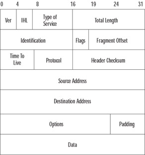
Figure 8.1: The IP Header
Let's quickly review the meaning of key fields in Figure 8.1. Most are not specifically part of the review exam, but it helps to put what the PIX does in context:
-
The protocol parameter indicates the upper-level protocol that is using IP. The decimal value for TCP is 6, and UDP is 17. The list of assigned numbers for this field is available at www.iana.org/assignments/protocol-numbers. Note that this field is important for access-list commands. The command syntax is:
access-list <acl_ID> {deny | permit} <protocol>…The protocol number here corresponds to this field. Note that you can specify the keyword tcp for type 6 or udp for type 17.
-
The source address and destination address fields are filled with the IP addresses of the respective devices; note that an IP address is four octets, so this can be viewed as a 32-bit number. You will see these numbers in the XLATE table.
Transmission Control Protocol
Many Internet services, such as HTTP, SMTP, or SSH, are based on TCP. This protocol provides reliable service by being connection-oriented and includes error detection and correction. The connection must be established before a data transfer can occur, and transfers are acknowledged throughout the process. Firewalls can identify the connection establishment and often interrupt that establishment as part of the protective mechanism. Acknowledgments assure that data is being received properly. The acknowledgment process provides robustness in the face of network congestion or communication unreliability. The acknowledgment has also been used to penetrate stateless firewalls; the PIX can identify packets that are not part of valid streams and block transmission. TCP also determines when the transfer ends and closes the connection, thus freeing resources on the systems. As noted earlier, the PIX watches for transfer end and acts appropriately. Checksums assure that the data has not been accidentally modified during transit. The PIX has the ability to rewrite checksums to handle NAT issues.
Figure 8.2 shows the format of the TCP header.
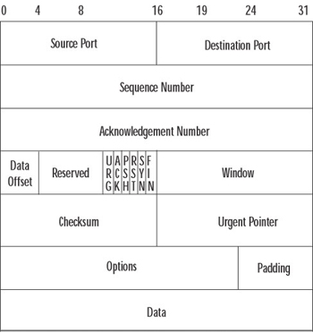
Figure 8.2: The TCP Header
The PIX inspects TCP packets for several fields, notably source port, destination port, sequence and acknowledgment numbers, and TCP flags. Notice that source and destination ports and information about the flags are listed in the CONN connections table.
The concept of port is common to both TCP and UDP (discussed in the following section). The idea is that for these types of protocols, we can identify an ordered pair (IP address and port), called a socket, with each side of the communication flow. Multiple communications from the same host (same IP) can be distinguished by different port numbers—thus different sockets. Sockets on the server generally have a "well-known port" number. The PIX has a mapping between well-known ports and their English equivalents.
We have enough background to see how ASA works for TCP connections. A TCP datastream begins with the "three-way handshake." The idea is for each side to set up the initial sequence number, a pointer that will describe the position in the datastream for each packet sent. The TCP flag that indicates a request to start that datastream is the SYN flag. The first three packets are an initial SYN request from the client to the server; then back from the server to the client with acknowledgment of the client's request (by setting the ACK flag) and the server's need to initialize as well (by setting the SYN flag); and finally the client back to the server, acknowledging the server's synchronization request. Therefore, from the TCP level, the path is SYN, SYN/ACK, ACK.
At the PIX, a little more goes on. Figure 8.3 provides a diagram for how information flows through the PIX. Let's follow the first two network packets.
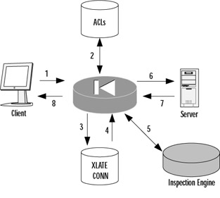
Figure 8.3: Basic ASA Operations
-
The client generates a SYN packet, headed toward the server, to establish a new connection.
-
The PIX investigates the ACL to determine if the information flow control policy should permit the new connection.
-
Assuming the connection is valid, the PIX updates the connections table.
-
The XLATE table is updated as necessary.
-
The stream is processed by the Application Inspection Engine, if necessary, which could involve rewriting the packet.
-
The packet is sent on to the server.
-
On the reverse path, the server responds with its SYN/ACK.
-
However, since this is not an initialization request, inspection of the rule base is not required; it looks the packet up in the connections table and then forwards it back to the client.
TCP Sequence Number Randomization
All that SYN and SYN/ACK work is designed so that both sides will agree on an initial sequence number (ISN) for each side of their communication. This adds a layer of security protection; in theory, one would have to be able to "hear" the TCP SYN request to know what ISN to use, and thus the IP address of the host in the datastream must be able to receive the packet, and therefore, for example, hosts on the Internet can't masquerade as local hosts.
Unfortunately, many servers use an easily guessed ISN generation function. One famous break-in, Kevin Mitnick's raid on Tsunomo Shinomura's data, chronicled in the book Takedown, was based on this flaw. The PIX provides protection against this type of attack by using TCP sequence number randomization. As the packets pass through the firewall, they are rewritten so that the ISNs cannot be predicted.
This system is not perfect; you should still use authentication and authorization at the server where available. However, it should provide an extra layer of protection that will let your security officers sleep better at night.
User Datagram Protocol
Several Internet applications, notably Domain Name Service (DNS) and many streaming audio and video protocols, are based on User Datagram Protocol (UDP). The UDP protocol is a simple, unreliable transport service. It is connectionless, so delivery is not assured. Look at the simple design of the UDP header in Figure 8.4 and you will understand this protocol's efficiency. Since connections aren't set up and torn down, there is very little overhead. Lost, damaged, or out-of-order segments will not be retransmitted unless the application layer requests it. UDP is used for fast, simple messages sent from one host to another. Due to its simplicity, UDP packets are more easily spoofed than TCP packets. If reliable or ordered delivery of data is needed, applications should use TCP.
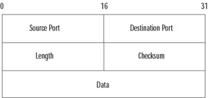
Figure 8.4: The UDP Header
There is usually a trade-off between simplicity and security, and this is true with UDP. Because TCP is connection oriented, we can identify the start of the session by unique flags—but as you can see in Figure 8.4, there aren't any flags here. All you have to work with is the UDP socket pairs.
This is where the firewall state comes in. The PIX has the ability to recognize the first UDP packet in a datastream. When the first packet is permitted by the information flow control policy (either because it is coming from a trusted net toward a less trusted one or because of an explicit exception in the ACL), the same sort of process shown in Figure 8.3 occurs. If permitted, an entry is made in the connections table, and further packets with the same socket pairs are associated with that authorized datastream until an idle timeout occurs. (The idle timeout is set with the timeout command and defaults to two minutes.)
Note that other protocols besides TCP and UDP are permitted. Most common is ICMP, the Internet Control Message Protocol. ICMP provides diagnostic functions and error reporting for IP. For example, ICMP can provide feedback to a sending host when a destination is unreachable or time is exceeded (TTL=0). A ping is an ICMP echo request message, and the response is an ICMP echo reply.
Other types of protocols are filtered by the PIX, although the concept of socket does not apply (and so you cannot specify extra parameters on the access list beyond filtering on the source and destination addresses). The special protocol 0 refers to any IP packet, and you can specify any value between 0 and 255. You can also use literals; you have already seen the literals TCP (which is 17), UDP (which is 6), and ICMP (which is 1).
These other protocols are handled similarly to the UDP approach, with idle timeouts removing entries from the connection table when they are no longer valid.
Advanced Protocol Handling
The PIX has taken elements from both camps in an example of a hybrid firewall, combining stateful packet filtering with advanced protocol handling with proxies via the fixup command. For common applications, the PIX provides advanced protocol handling, not only dealing with embedded IP addresses (the scourge of NAT functionality) but improving overall security handling.
Providing support for complex protocols is a distinguishing characteristic of the PIX. The "fixup" proxies include ftp, http, h323, ils, rsh, rtsp, smtp, sip, skinny, and SQL. Some protocols, such as DNS Guard (which prevents multiple DNS responses from penetrating to the host), are supported in the native PIX services and do not need to be configured.
Application support of this type is where the real power of a firewall shines. The PIX is more than just a gatekeeper, passing or blocking packets; it understands the underlying protocol and actively rewrites the communications—enforcing RFCs, eliminating dangerous commands, and preventing the leakage of information—to provide the highest level of security available, consistent with application functionality.
VPN Support
An important aspect of network security is confidentiality of information. Packets flowing along a network are much like postcards sent through the mail; if you don't want the world reading your messages, you have to take additional care.
To achieve the kind of confidentiality offered on a private network, several approaches have been followed. One is to use encryption to conceal the information. An early standard, followed by Microsoft, is the Point-to-Point Tunneling Protocol (PPTP). Much like putting a letter inside a sealed envelope, this standard allows encapsulating (and concealing) network traffic inside a transport header. A similar but more comprehensive approach is to use the Layer 2 Tunneling Protocol (L2TP). This protocol is native to many Microsoft deployments, and so the PIX's support for PPTP and L2TP is an important element of the feature set.
In the fall of 1998, the Security Architecture for IP (IPsec) was published in RFC2401. Cisco has provided a leadership position in IPsec implementation, having co-authored many of the IPsec RFCs as well as providing solutions for some of the stickier IPsec issues, such as NAT traversal. It should be no surprise that the PIX is an excellent IPsec tunnel terminator. It has a wide range of interoperable standards and is straightforward to configure with pre-shared keys or with a certificate authority (CA). Many companies are using the PIX as an integrated firewall/VPN terminator, particularly in SOHO environments, as well as a stand-alone VPN terminator in conjunction with another (dedicated) firewall.
One of the PIX's best features is VPN performance. The models are designed to produce essentially wire-speed performance under heavy IPsec load. Because of the simplicity of the appliance's maintenance, VPN termination on a PIX is a sound choice for many enterprise or carrier-class environments.
URL Filtering
A uniform resource locator, or URL, is the way we identify addresses for information on the World Wide Web (WWW). The PIX firewall supports URL filtering by capturing a request and querying a database located on an N2H2 or Websense server. The N2H2 server can be running Linux (see www.n2h2.com/products/bess.php?os=lnx&device=pix) or Microsoft Windows (see www.n2h2.com/products/bess.php?os=win&device=pix); the Websense server can use these platforms or be installed on a Solaris server (www.websense.com/products/integrations/ciscoPIX.cfm).
URL filtering provides you with a way to apply an acceptable use policy for Internet browsing as well as to capture and analyze how your personnel are using the Internet. The servers themselves provide reporting capabilities so that you can determine how well your policy is being followed.
NAT and PAT
Another key strength of the Cisco PIX is its ability to translate addresses. Historically, an insider note is that the PIX comes from equipment created by a company called Network Translations Inc., and the PIX's first role was simply to perform address translation. (The name PIX comes from Private Internet Exchange, reflecting its purpose: to exchange traffic between private networks and the Internet.)
Network Address Translation, or NAT, encapsulates the idea that we can remap IP addresses (or sockets) where desirable in order to provide efficiencies or security. In the late 1990s, there was a great concern that we would run out of IP addresses; every host needed its own IP, and there are only 232 to go around. Once we hit that number of computers, we'd be out of addresses. Worse, when you changed service providers, you generally had to give up your IP addresses and renumber all your machines—an expensive, time-consuming task that often ended up missing some machines, leaving them unable to communicate.
An idea was developed to use "private" addresses internally and, at the perimeter of our control, remap them into "public" addresses given to us by our service provider. Now we do not have to spend a lot of time renumbering our IP addresses; if we change providers, we only have to change the value of the IP addresses on the external firewalls and we are done. In February 1996, Cisco co-authored RFC1918, which established ranges for "private" addresses—all of the 10 network (10.0.0.0 through 10.255.255.255), part of the 172 network (172.16.0.0 through 172.31.255.255), and the 192.168 network (192.168.0.0 through 192.168.255.255). This RFC is followed nearly universally by enterprises today, with IP address schemes chosen from these private networks to simplify the structure of the internal network.
NAT also provides a form of security through obscurity. Since the private addresses are not advertised, an outside attacker does not necessarily know how the machine refers to itself; this structure adds an extra layer of work the attacker needs to perform to understand how to connect to an internal host.
There are several different ways to perform the address translation. The simplest form of NAT provides a one-to-one map between internal host IP addresses and external addresses—for example, a map between 10.1.1.1 and 198.133.219.25. Then, any reference, say 198.133.219.25 port 80, gets translated to 10.1.1.1 port 80, and vice versa. This form of NAT has two different flavors: static NAT, in which the translation is set up once and is permanent, and dynamic NAT, in which a translation is set up from a pool of available addresses and is torn down when an idle timeout occurs. The former is perfect for remapping servers that need to provide consistent access to the outside world; because the translated address is fixed, it can be put into public DNSs and readily accessed by outside clients. The latter is perfect for remapping users who need public services and IP addresses for a short time, which can then can be released for other users when the services and addresses are no longer needed. This system allows for, say, 100 people to hide behind 30 addresses, as long as no more than 30 of those people need external access at any one time.
The idea of dynamic NAT can be extended even further. Most IP services are based on sockets, such as IP address/port number pairs. Rather than remapping on IP address, we can remap on sockets. Now 10.1.1.1,80 might get mapped to 198.133.219.25,3125 while 10.1.3.42,80 gets mapped to 198.133.219.25,4176—the same IP address in both cases, but because the port numbers are different, the sockets are different. Therefore, the other side of the conversation would be able to distinguish between these two datastreams.
This concept is called Port Address Translation (PAT) and allows for stacking over 30,000 TCP sessions on a single IP address. The good news is that now when you want to hide your 100 users, you can hide them behind a single IP address. The bad news is that certain protocols—ones that expect fixed port addresses—are broken by this translation. The PIX can be configured to use static addresses for fixed servers and dynamic addresses for users with an overflow pool of PAT (or even multiple PAT to give a better chance of being able to preserve port address). You can see that the PIX is a very flexible and highly effective network address translation device.
High Availability
The three fundamental concepts of information security are confidentiality, integrity, and availability. The PIX addresses the availability idea by providing a robust, fault-tolerant environment. Fault-tolerant means that if something goes wrong, alarms are set off and something is done to ameliorate the problem.
The term high availability usually refers to hardware fault tolerance. Obviously, a firewall is a critical piece of equipment: By its very nature, it has to stand in the center of the traffic flow. Cisco hardware is of very high quality, and the PIX has no moving parts, but sometimes equipment does fail. High availability is a device configuration so that isolated failure of the hardware will not bring down your network.
To achieve this goal, of course, you must have multiple pieces of hardware. In this case, two PIXs are configured similarly, and they communicate between each other. If one piece of hardware dies, the other transparently picks up the traffic, and alarm messages are sent to the network management console.
High availability can be configured in several ways. Naturally, you need a second PIX that will be configured in a hot standby fashion. The simplest and least expensive way is through a serial cable, provided when you purchase the failover license. Alternately, a LAN interface can be dedicated to the failover process. With the failover cable, hello packets containing the number of bytes seen by the interfaces are transmitted between the two boxes, and if the values differ, failover can occur. With the LAN interface, full state information is transmitted so that in the event of a failover, the TCP sessions can keep running without reinitialization.
|
EAN: 2147483647
Pages: 240