Policy-Based IDS
|
When defining rules or attack signatures for an IDS operating normally, you define which attack signatures you don't want to see on your network. For example, if a new attack comes out, you would add its signature to your IDS because you want to be alerted if a packet containing that signature is seen on your network. In other words, you don't want to see a packet with this signature on your network because it indicates that an attack of a specific type is being performed. Following this process and performing frequent rule updates allows your IDS to constantly watch for the latest attacks.
By operating in this fashion, your IDS is constantly playing catch-up with intruders. When a new attack is performed somewhere in the world, you have to wait for a signature for the attack to be determined, and then add it to the rules for your IDS. During this time, the attack could conceivably happen to your network and you wouldn't be aware of it. This is one of the principal problems with normal intrusion detection.
Policy-based IDS is almost a complete reversal of normal intrusion detection. With policy-based IDS, the IDS administrator defines what is normal and acceptable behavior for the network. This can include communication of specific types between specific hosts, specific protocols, and so forth. The benefit of defining this policy is that the administrator is able to set baselines of what "normal" operations for the network should look like. This information can then be used to determine what unusual behavior is.
The concept behind policy-based IDS is that whatever is not included as part of the list of acceptable behavior is potentially an intrusion. The IDS administrator goes through the often long and arduous process of determining what should not trigger an alert. Then, the IDS sends an alert on anything not previously defined by the administrator as acceptable traffic.
Using a policy-based IDS has several advantages over normal IDSs. A policy-based IDS can be used to determine whether your firewall is performing properly by checking the network to see if traffic that should have been blocked at the firewall has made it to the internal network. This provides an added layer of redundancy to your existing security system by allowing you to be notified in the event of an unexpected failure. This also works with other security systems in place besides firewalls, such as ensuring that switches have not become susceptible to an Address Resolution Protocol (ARP) spoofing attack, and so forth.
Another very beneficial aspect of using a policy-based IDS is that it can be used to detect new and previously undocumented attacks. Whereas a normal IDS is reactive based on its predefined rules, a properly configured policy-based IDS is proactive in that it will alert you to any unexpected activities on the network. This can allow you to diagnose a new form of attack that might not have been detected by a standard or typical IDS.
In many cases, a policy-based IDS can make you aware of an attack faster than a typical IDS can. Since there are typically fewer rules involved in defining acceptable traffic compared to the number of rules necessary to define all known attack signatures, a policy-based IDS can sometimes outperform a normal IDS. Additionally, sometimes the start of an attack might not necessarily match a known attack signature, but it might be flagged as unusual behavior to a policy-based IDS. This can allow you to head off an attack before it occurs.
Defining a Network Policy for the IDS
The first step in setting up a policy-based IDS is to define your network policy. This should be a very detailed policy specifying exactly what is allowable on the network. This can include communication between specific systems, the use of specific protocols on the network, and so forth. The main point to keep in mind when defining this policy is that any traffic that does not conform to your policy of allowable behavior will be considered suspicious and will trigger an alert. You don't want your policy to be so stringent that you get alerts every few minutes, nor so lax that you miss an actual attack. Getting this policy defined properly is the most difficult task in setting up your policy-based IDS.
When defining your policy, you can determine your allowable traffic based on IPs, protocols, ports, and so forth. As the first part of your policy definition, you need to be aware of what devices are communicating on your network and how they are communicating. For example, if you have a Web server communicating on your network, you will need to know what its IP is and the ports on which it is publishing. The best way to start this process is to inventory your systems and determine what their purposes are. In a large enterprise, this is a huge task, but it can be fairly easy in smaller networks. For example purposes, we will create a fictional network with a number of servers and clients to demonstrate the definition of a network policy. Figure 31.1 is the network diagram illustrating our environment.
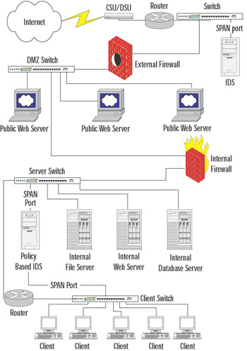
Figure 31.1: Network Diagram
While the diagram in Figure 31.1 is fairly complex, it shows a very basic, well-designed network for a small office with a public Web presence and plans for future growth. The clients are connected to a dedicated switch, which is in turn connected to a router and another dedicated switch used for the environment's servers. A system functioning as a policy-based IDS is connected to SPAN ports on each of these switches, using two interfaces to perform IDS functions for both networks. The dedicated server switch has a few servers attached to it and a connection to the internal firewall. This firewall separates the DMZ from the internal network and functions as a router.
Within the DMZ, there are three publicly accessible Web servers. These servers and the externally facing port on the internal firewall are connected to a switch for the DMZ network. Also attached to this switch is the internally facing port on the external firewall. The externally facing port of the external firewall is connected to yet another switch that also has connections to the router for the CSU/DSU and a normal IDS.
Many modifications can be made to this design to improve security, such as adding another firewall situated between the CSU/DSU and the switch; however, this design is fairly typical in most small organizations. Additional security usually involves additional funds that are not always available. For the purpose of example in this section, we will be referring back to this diagram regularly.
To design our policy, we'll assume that this diagram shows every entity connected to our network. In reality, there are usually a few rogue systems of which the administrators are not aware, but we'll discuss how to find those later in this section.
The next step in defining our network policy is to determine what traffic is acceptable between these known hosts. We'll start with the client/server communications. First, there is the internal network's file server. In this network, we'll assume that this is a standard Microsoft Windows 2000 server hosting a file share for the network. It is probably also performing authentication for the network to grant access to its files. Table 31.1 lists the ports used by a Windows 2000 server based on Microsoft Knowledge Base article 150543.
| Function | Static Ports |
|---|---|
| Browsing | UDP:137,138 |
| DHCP Lease | UDP:67,68 |
| DHCP Manager | TCP: 135 |
| Directory Replication | UDP:138 TCP:139 |
| DNS Administration | TCP: 135 |
| DNS Resolution | UDP: 53 |
| Event Viewer | TCP: 139 |
| File Sharing | TCP: 139 |
| Logon Sequence | UDP:137,138 TCP:139 |
| NetLogon | UDP: 138 |
| Pass Through Validation | UDP:137,138 TCP:139 |
| Performance Monitor | TCP: 139 |
| PPTP | TCP: 1723 IP:47 |
| Printing | UDP: 137,138 TCP:139 |
| Registry Editor | TCP: 139 |
| Server Manager | TCP: 139 |
| Trusts | UDP: 137,138 TCP:139 |
| User Manager | TCP: 139 |
| WinNT Diagnostics | TCP: 139 |
| WinNT Secure Channel | UDP: 137,138 TCP:139 |
| WINS Replication | TCP: 42 |
| WINS Manager | TCP: 135 |
| WINS Registration | TCP: 137 |
| SMB | TCP,UDP: 445 |
| ISAKMP (IPSec) | UDP: 500 |
| ESP (IPSec) | IP: 50 |
| AH (IPSec) | IP: 51 |
| Kerberos | TCP,UDP: 88 |
| RSVP | IP: 46 |
Based on the port information shown in Table 31.1, we can determine that the clients will need to be able to communicate to this server on a number of these ports. Now, let's assume that all of these services might be needed at some point. That leads us to the conclusion that the clients will need to communicate with the file server on the ports listed in Table 31.2.
| IP | TCP | UDP |
|---|---|---|
| 46 | 42 | 53 |
| 47 | 88 | 67 |
| 50 | 135 | 68 |
| 51 | 137 | 88 |
| 139 | 137 | |
| 445 | 138 | |
| 1723 | 445 | |
| 500 |
Now that we have determined the communication needs of the clients for connecting to the file server, let's work on the remaining servers. The next server in our diagram is an internal Web server. Assuming that all traffic to this server is using either HTTP or HTTPS on their standard ports, we'll simply need to allow traffic to TCP ports 80 and 443 on this server. Our last server is an internal database server, and we'll assume that it is running Microsoft SQL Server. If this is the case, communication to the server will take place over TCP port 1433 by default. Allowing traffic to this server on TCP port 1433 will take care of the client communication needs.
It looks like we have a handle on the communication from the clients to the servers, so let's look at communication from the servers back to the clients. In most cases when using Microsoft Windows, a client system will open a TCP or UDP connection to a remote system using a port between 1024 and 5000. This can be changed by modifying the Registry of the Windows client. Other operating systems use different standards, but for this example we'll assume that non-modified Windows clients are in use. Based on this, we will assume that any traffic between the server subnet and the client subnet on these ports is acceptable. In addition, some of the clients might be running some Windows services, so we'll also apply the port list from Table 31.2 to the client systems and the servers.
At this point, we have basically defined our network policy and just need to put it all together. We've defined communication with each device, so let's see what we have determined to be acceptable traffic:
-
Clients to file server on ports defined in Table 31.2
-
Clients to Web server on TCP ports 80 and 443
-
Clients to database server on TCP port 1433
-
Servers to clients on TCP and UDP ports 1024 through 5000
-
-
Servers to clients on ports defined in Table 31.2
Anything outside this list will be deemed unacceptable traffic when we define the rules for our policy-based IDS. In truth, we certainly have not captured every port that will be used, but this will give us a baseline for determining what else is acceptable. We'll discuss the process of fine-tuning in the section "Policy-Based IDS in Production".
An Example of Policy-Based IDS
Since we have now defined our basic network policy, we'll move on to how to actually use this information. Our first step is to translate this policy into actual Snort rules. As previously mentioned, using a policy-based IDS is really the reverse of normally running an IDS. Therefore, we have to pass a parameter to Snort to cause it to process the rules in a different order.
By default, Snort processes alert rules first, followed by pass rules. For our needs, we will have to force Snort to process pass rules before alert rules. Otherwise, we would receive an alert on all traffic, as Snort would not even check to see if it was acceptable based on our pass rules. Using the -o command-line parameter when starting Snort will cause it to process the pass rules before the alert rules. For example, you could start Snort using the following command:
./snort -c /etc/snort/snort.conf -o
We also need to add an entry to our snort.conf file to point to a new rule file. This is simply another include statement in the rules section of the snort.conf file. Add the following line to the file:
include $RULE_PATH/policy-based.rules
The policy-based.rules file will hold all of the rules we define for our policy-based IDS. The first step in defining this set of rules is to set up the alert rules. In this case, we want to generate alerts on any TCP, UDP, or IP-based traffic that is not explicitly defined in a pass rule. The following code shows how we would configure these alert rules in the policy-based.rules file:
# $Id: policy-based.rules,v 1.0 2003/02/08 16:00:00 jeremyfaircloth Exp $ # ———————— # POLICY BASED RULES # ———————— # These rules are defined for policy based intrusion detection. # # Alert Rules # This will alert on ANY TCP connections on these subnets alert tcp any any <> [10.10.10.0/24,10.10.11.0/24] any # This will alert on ANY UDP connections on these subnets alert udp any any <> [10.10.10.0/24,10.10.11.0/24] any # This will alery on ANY IP connections on these subnets alert ip any any <> [10.10.10.0/24,10.10.11.0/24] any
In this rules file, we first define an alert for TCP traffic from any IP and any port going to or from two subnets on any port. These two subnets, 10.10.10.0/24 and 10.10.11.0/24, are our client and server subnets, respectively. We then duplicate the rule to cover the UDP and IP protocols. With the alert rules defined in this manner, we will receive an alert on every connection attempt in these two subnets.
Next, we have to transform our previously defined network policy into Snort rules. Let's go over our network policy again. There are five specific directives in our policy on which traffic is permissible:
-
Clients to file server on ports defined in Table 31.2
-
Clients to Web server on TCP ports 80 and 443
-
Clients to database server on TCP port 1433
-
Servers to clients on TCP and UDP ports 1024 through 5000
-
-
Servers to clients on ports defined in Table 31.2
The first order of business is to define rules that allow the systems on the client subnet (10.10.10.0/24) to communicate with the file server (10.10.11.1) on the specific ports defined in Table 31.2. We'll begin with IP traffic, and then move on to TCP and UDP. For IP ports 46, 47, 50, and 51, we can define the pass rules in two lines and cover only these specific ports. We could cover the range of ports 46 through 50 in a single rule, but we want to be as restrictive as possible.
pass ip 10.10.10.0/24 any -> 10.10.11.1 46:47 pass ip 10.10.10.0/24 any -> 10.10.11.1 50:51
These rules tell Snort to allow any traffic from the 10.10.10.0/24 subnet from any port to 10.10.11.1 ports 46, 47, 50, and 51 to pass and not signal an alert. From here, we'll move on to defining the rules for TCP communication to the file server. We'll define the rules in the same manner, but use TCP rather than IP. These rules should look like the following:
pass tcp 10.10.10.0/24 any -> 10.10.11.1 42 pass tcp 10.10.10.0/24 any -> 10.10.11.1 88 pass tcp 10.10.10.0/24 any -> 10.10.11.1 135 pass tcp 10.10.10.0/24 any -> 10.10.11.1 137 pass tcp 10.10.10.0/24 any -> 10.10.11.1 139 pass tcp 10.10.10.0/24 any -> 10.10.11.1 445 pass tcp 10.10.10.0/24 any -> 10.10.11.1 1723
Again, these rules simply tell Snort to allow any traffic from the 10.10.10.0/24 subnet from any port to 10.10.11.1 on the specific ports defined to pass without generating an alert. We'll do the same for the UDP ports shown in Table 31.2:
pass udp 10.10.10.0/24 any -> 10.10.11.1 53 pass udp 10.10.10.0/24 any -> 10.10.11.1 67:68 pass udp 10.10.10.0/24 any -> 10.10.11.1 88 pass udp 10.10.10.0/24 any -> 10.10.11.1 137:138 pass udp 10.10.10.0/24 any -> 10.10.11.1 445 pass udp 10.10.10.0/24 any -> 10.10.11.1 500
We've now defined all of the rules necessary to achieve objective one of our network policy. The following code shows all of these rules.
# Rules for Network Policy Objective One pass ip 10.10.10.0/24 any -> 10.10.11.1 46:47 pass ip 10.10.10.0/24 any -> 10.10.11.1 50:51 pass tcp 10.10.10.0/24 any -> 10.10.11.1 42 pass tcp 10.10.10.0/24 any -> 10.10.11.1 88 pass tcp 10.10.10.0/24 any -> 10.10.11.1 135 pass tcp 10.10.10.0/24 any -> 10.10.11.1 137 pass tcp 10.10.10.0/24 any -> 10.10.11.1 139 pass tcp 10.10.10.0/24 any -> 10.10.11.1 445 pass tcp 10.10.10.0/24 any -> 10.10.11.1 1723 pass udp 10.10.10.0/24 any -> 10.10.11.1 53 pass udp 10.10.10.0/24 any -> 10.10.11.1 67:68 pass udp 10.10.10.0/24 any -> 10.10.11.1 88 pass udp 10.10.10.0/24 any -> 10.10.11.1 137:138 pass udp 10.10.10.0/24 any -> 10.10.11.1 445 pass udp 10.10.10.0/24 any -> 10.10.11.1 500
Now, let's move on to the second objective in our network policy. We need to define rules that allow the client systems to communicate with the internal Web server. We'll set the internal Web server IP as 10.10.11.11, and the client systems are still on subnet 10.10.10.0/24. Based on this information, these rules are very simple to define. Since we're just using TCP, we define the rules as follows:
pass tcp 10.10.10.0/24 any -> 10.10.11.11 80 pass tcp 10.10.10.0/24 any -> 10.10.11.11 443
Those two simple rules cover the second objective of the network policy and allow traffic originating from any port on the 10.10.10.0/24 subnet directed to ports 80 or 443 to pass without generating an alert. The third objective is just as easy and only requires one rule. We need to allow the clients to communicate with the database server on TCP port 1433. In this fictitious network, we'll put our database server at IP 10.10.11.21.
pass tcp 10.10.10.0/24 any -> 10.10.11.21 1433
Objective four of our network policy defines traffic going in the other direction, from the servers to the clients. For this objective, we need to allow the servers to connect back to the clients on TCP and UDP ports 1024 through 5000. These rules are fairly simple to define, as we can easily specify more than one source IP address.
pass tcp [10.10.11.1,10.10.11.11,10.10.11.21] any -> 10.10.10.0/24 1024:5000 pass udp [10.10.11.1,10.10.11.11,10.10.11.21] any -> 10.10.10.0/24 1024:5000
The rules we've defined now meet the first four objectives of the network policy. The fifth objective is a little trickier—we must allow the servers to communicate back to the clients on the ports defined in Table 31.2. We can do this in a number of ways. We could simply allow all communication between the server subnet and the client subnet on these ports to be allowed. Alternatively, we could define the specific server IPs and allow any traffic from the servers to the client subnet on these ports to pass. Finally, we could define the IPs of the servers and the clients and allow traffic from the specific server IPs to the specific client IPs on these ports to pass.
Since in our previous rules we allowed traffic from the entire client subnet to pass to the servers, we'll do the same here and take the second option. This allows for easier rule definition, yet gives us a good level of security. In addition, this allows for future growth in the number of client systems that is typically more likely than growth in server systems. The following shows the five rules that we defined to meet this objective:
# Rules for Network Policy Objective Five pass ip [10.10.11.1,10.10.11.11,10.10.11.21] any -> 10.10.10.0/24 46:47 pass ip [10.10.11.1,10.10.11.11,10.10.11.21] any -> 10.10.10.0/24 50:51 pass tcp [10.10.11.1,10.10.11.11,10.10.11.21] any -> 10.10.10.0/24 42 pass tcp [10.10.11.1,10.10.11.11,10.10.11.21] any -> 10.10.10.0/24 88 pass tcp [10.10.11.1,10.10.11.11,10.10.11.21] any -> 10.10.10.0/24 135 pass tcp [10.10.11.1,10.10.11.11,10.10.11.21] any -> 10.10.10.0/24 137 pass tcp [10.10.11.1,10.10.11.11,10.10.11.21] any -> 10.10.10.0/24 139 pass tcp [10.10.11.1,10.10.11.11,10.10.11.21] any -> 10.10.10.0/24 445 pass tcp [10.10.11.1,10.10.11.11,10.10.11.21] any -> 10.10.10.0/24 1723 pass udp [10.10.11.1,10.10.11.11,10.10.11.21] any -> 10.10.10.0/24 53 pass udp [10.10.11.1,10.10.11.11,10.10.11.21] any -> 10.10.10.0/24 67:68 pass udp [10.10.11.1,10.10.11.11,10.10.11.21] any -> 10.10.10.0/24 88 pass udp [10.10.11.1,10.10.11.11,10.10.11.21] any -> 10.10.10.0/24 137:138 pass udp [10.10.11.1,10.10.11.11,10.10.11.21] any -> 10.10.10.0/24 445 pass udp [10.10.11.1,10.10.11.11,10.10.11.21] any -> 10.10.10.0/24 500
The rules defined here are similar to the rules we defined for traffic coming from the client subnet to the file server. The main difference is that these rules define the source IPs of all of the servers and a destination IP of the client subnet. Otherwise, the port definitions are identical and the functionality of the rules is the same.
We've now covered all of the objectives of our network policy. Each of the five objectives has been translated into Snort rules and defined in our policy-based.rules file. The contents of this file are shown in the following output:
# $Id: policy-based.rules,v 1.0 2003/02/08 16:00:00 jeremyfaircloth Exp $ # ———————— # POLICY BASED RULES # ———————— # These rules are defined for policy based intrusion detection. # # Alert Rules # This will alert on ANY TCP connections on these subnets # alert tcp any any <> [10.10.10.0/24,10.10.11.0/24] any # This will alert on ANY UDP connections on these subnets # alert udp any any <> [10.10.10.0/24,10.10.11.0/24] any # This will alery on ANY IP connections on these subnets alert ip any any <> [10.10.10.0/24,10.10.11.0/24] any # # # Pass Rules # These rules define acceptable network traffic # Rules for Network Policy Objective One pass ip 10.10.10.0/24 any -> 10.10.11.1 46:47 pass ip 10.10.10.0/24 any -> 10.10.11.1 50:51 pass tcp 10.10.10.0/24 any -> 10.10.11.1 42 pass tcp 10.10.10.0/24 any -> 10.10.11.1 88 pass tcp 10.10.10.0/24 any -> 10.10.11.1 135 pass tcp 10.10.10.0/24 any -> 10.10.11.1 137 pass tcp 10.10.10.0/24 any -> 10.10.11.1 139 pass tcp 10.10.10.0/24 any -> 10.10.11.1 445 pass tcp 10.10.10.0/24 any -> 10.10.11.1 1723 pass udp 10.10.10.0/24 any -> 10.10.11.1 53 pass udp 10.10.10.0/24 any -> 10.10.11.1 67:68 pass udp 10.10.10.0/24 any -> 10.10.11.1 88 pass udp 10.10.10.0/24 any -> 10.10.11.1 137:138 pass udp 10.10.10.0/24 any -> 10.10.11.1 445 pass udp 10.10.10.0/24 any -> 10.10.11.1 500 # Rules for Network Policy Objective Two pass tcp 10.10.10.0/24 any -> 10.10.11.11 80 pass tcp 10.10.10.0/24 any -> 10.10.11.11 443 # Rules for Network Policy Objective Three pass tcp 10.10.10.0/24 any -> 10.10.11.21 1433 # Rules for Network Policy Objective Four pass tcp [10.10.11.1,10.10.11.11,10.10.11.21] any -> 10.10.10.0/24 1024:5000 pass udp [10.10.11.1,10.10.11.11,10.10.11.21] any -> 10.10.10.0/24 1024:5000 # Rules for Network Policy Objective Five pass ip [10.10.11.1,10.10.11.11,10.10.11.21] any -> 10.10.10.0/24 46:47 pass ip [10.10.11.1,10.10.11.11,10.10.11.21] any -> 10.10.10.0/24 50:51 pass tcp [10.10.11.1,10.10.11.11,10.10.11.21] any -> 10.10.10.0/24 42 pass tcp [10.10.11.1,10.10.11.11,10.10.11.21] any -> 10.10.10.0/24 88 pass tcp [10.10.11.1,10.10.11.11,10.10.11.21] any -> 10.10.10.0/24 135 pass tcp [10.10.11.1,10.10.11.11,10.10.11.21] any -> 10.10.10.0/24 137 pass tcp [10.10.11.1,10.10.11.11,10.10.11.21] any -> 10.10.10.0/24 139 pass tcp [10.10.11.1,10.10.11.11,10.10.11.21] any -> 10.10.10.0/24 445 pass tcp [10.10.11.1,10.10.11.11,10.10.11.21] any -> 10.10.10.0/24 1723 pass udp [10.10.11.1,10.10.11.11,10.10.11.21] any -> 10.10.10.0/24 53 pass udp [10.10.11.1,10.10.11.11,10.10.11.21] any -> 10.10.10.0/24 67:68 pass udp [10.10.11.1,10.10.11.11,10.10.11.21] any -> 10.10.10.0/24 88 pass udp [10.10.11.1,10.10.11.11,10.10.11.21] any -> 10.10.10.0/24 137:138 pass udp [10.10.11.1,10.10.11.11,10.10.11.21] any -> 10.10.10.0/24 445 pass udp [10.10.11.1,10.10.11.11,10.10.11.21] any -> 10.10.10.0/24 500
Policy-Based IDS in Production
At this point, you've modified the snort.conf file to include the new policy-based.rules file. You've also created the policy-based.rules file and the rules to implement our network policy. Now it's time to start Snort and put the rules into action.
We discussed previously that Snort has to be started with the -o parameter to cause the pass rules to be processed before the alert rules. Assuming that the snort.conf file is in /etc/snort, start Snort using this syntax:
# snort -c /etc/snort/snort.conf -o
If your configuration is correct and there are no errors in the new rules, Snort should successfully start and begin scanning. It should be noted from the start screen (unless you're running in daemon mode) that Snort is indeed processing the pass rules before the alert rules, as shown in the following output.
Running in IDS mode Log directory = /var/log/snort Initializing Network Interface any --== Initializing Snort ==-- Rule application order changed to Pass->Alert->Log Initializing Output Plugins! Decoding 'ANY' on interface any Initializing Preprocessors! Initializing Plug-ins! Parsing Rules file /etc/snort/snort.conf
With Snort now actively scanning, you can refine your rules based on the reality of the traffic on your network. While the rules that we have defined cover the expected traffic on your network, there is always unexpected traffic that is probably acceptable. The process of actively monitoring your alert log during this burn-in period allows you to fine-tune your rules.
For example, during a review of your alert log, you see the following entries:
[**] Snort Alert! [**] [Priority: 0] 02/09-15:49:03.042888 10.10.10.1:3137 -> 10.10.11.21:21 TCP TTL:128 TOS:0x0 ID:33435 IpLen:20 DgmLen:48 DF ******S* Seq: 0x57E7A50F Ack: 0x0 Win: 0x4000 TcpLen: 28 TCP Options (4) => MSS: 1460 NOP NOP SackOK [**] Snort Alert! [**] [Priority: 0] 02/09-15:49:05.946778 10.10.10.1:3137 -> 10.10.11.21:21 TCP TTL:128 TOS:0x0 ID:33572 IpLen:20 DgmLen:48 DF ******S* Seq: 0x57E7A50F Ack: 0x0 Win: 0x4000 TcpLen: 28 TCP Options (4) => MSS: 1460 NOP NOP SackOK [**] Snort Alert! [**] [Priority: 0] 02/09-15:49:11.963321 10.10.10.1:3137 -> 10.10.11.21:21 TCP TTL:128 TOS:0x0 ID:33848 IpLen:20 DgmLen:48 DF ******S* Seq: 0x57E7A50F Ack: 0x0 Win: 0x4000 TcpLen: 28 TCP Options (4) => MSS: 1460 NOP NOP SackOK
These log entries indicate that one of the client systems is attempting to connect to the Web server using port 21. This is the well-known port used for FTP, so apparently someone is trying to use FTP to connect to the Web server. Following up on this, you might find that the Web content developer uses FTP to upload new content to the Web server. If management approves this operation, you'll need to modify your network policy to include this objective. In addition, you'll need to create a new rule to indicate that this is acceptable traffic for Snort. This rule could be defined as:
# Rules for Network Policy Objective Six pass tcp 10.10.10.1 any -> 10.10.11.21 21
You will run into many of these exceptions during the burn-in period of your policy-based IDS. Tuning your IDS might take quite a while, depending on the number of systems on the network, the type of work being performed, and many other factors. Moreover, adding and modifying rules is a nonstop administrative effort. There will always be something new added to the network or some new service added to an existing system. The ongoing modifications of this system might be tedious, but they do offer a high level of security to your environment.
It should be noted that we did not remove any of the existing rules from Snort when we configured the system to operate as a policy-based IDS. When you are using a policy-based IDS, it is still important to process normal IDS rules as well. Many attacks could easily slip by the policy-based rules that we defined, but the normal IDS rules would catch these attacks. For example, our policy-based rules do not define any restrictions on ICMP traffic. That leaves the door open for an ICMP (ping) flood attack.
In addition, we are allowing traffic to port 80 on the Web server, but the policy-based rules are not scanning the content of those packets. There is a problem here in that the IDS is now configured to process pass rules before alert rules. That means that even if there is malicious content inside a packet destined for the Web server, the IDS will not generate an alert.
The only real solution to this problem is to run one IDS in policy-based mode and the other normally, or creating a new rule action. In our fictitious network design, we haven't done this because it's unlikely that someone would attack the internal Web servers from the internal network, but it could happen. To add an additional layer of security, you can simply add another IDS into the mix or create a new rule action in your rules file:
##### ruletype passgood { type alert output log_null } ruletype everything { type log output log_tcpdump: suspicious.log } config order: alert passgood everything # insert all your normal rules here passgood tcp any any <> $HTTP_SERVERS $HTTP_PORTS passgood tcp any any <> $SMTP_SERVERS 25 passgood tcp any any <> $DNS_SERVERS 53 passgood udp any any <> $DNS_SERVERS 53 everything ip any any <> any any The primary disadvantage to implementing a policy based IDS is the amount of time and effort necessary to define the policy as to what behavior is acceptable. This is fairly simple in a small network, but in a large enterprise, it can be a very daunting task. Sometimes using a policy-based IDS isn't feasible due to the size of the network or the amount of administrative effort required to maintain the IDS. Keep in mind that the combination of a policy-based IDS and a normal IDS can provide for an incredibly high level of security, but it's not always possible to implement this strategy.
|
EAN: 2147483647
Pages: 240