Nokia IPSO Clustering
|
ClusterXL is not available for the Nokia platform. This is because Nokia provides its own HA and load-sharing solutions. In this section, we look at the load-sharing cluster solution that Nokia provides on IPSO 3.6-FCS4, how to configure it, and how to configure FireWall-1 NG FP3 so that you have a complete Nokia load-sharing solution. We then talk about how you can test the cluster and go over any special considerations for this solution.
Nokia Configuration
To configure a Nokia load-sharing cluster, you need to take the following steps:
-
Configure the interfaces of a Nokia.
-
Configure FireWall-1.
-
Configure clustering in Voyager.
We assume that you have installed IPSO 3.6 FCS-4 on your Nokia and that you have the Check Point FireWall-1 NG FP3 package installed and configured. As with setting up all clusters, it is recommended that you complete and test the physical connectivity first so that any problems that you encounter later aren't due to a misconfigured switch or interface, because these could be difficult to spot later.
In our example shown in Figure 21.51, you can see a sample Nokia cluster topology.
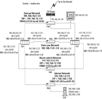
Figure 21.51: Our Example Nokia Clustering Topology Setup
The main difference in network topology between Nokia clustering and using Check Point ClusterXL is that you require a dedicated network for Nokia cluster control communications. This is in addition to the Check Point state sync network.
As you can see from Figure 21.51, each network that has a VIP also has a virtual MAC address—a multicast MAC that is used for the VIP. From a network perspective of neighboring equipment on the same network as the cluster interfaces, it looks very similar to Check Point ClusterXL in Load-Sharing mode.
You should ensure that you have configured all of the following using Voyager on each of the cluster members:
-
Make sure that interface speeds are consistent across host and switches on the subnet. Only use full-duplex where connected directly to full-duplex-enabled switches!
-
Make sure you have entries in each hosts file for the FireWall-1 management station and the other modules in the cluster.
-
Make sure you have the correct time and date and the correct default local for each member in the cluster and on the Check Point management station.
-
Make sure that the FireWall-1 NG FP3 package is installed.
-
Read the Nokia IPSO and Check Point NG FP3 release notes!
A Few Points about Installing an Initial Configuration of NG FP3 on Nokia IPSO
Installing software packages on the Nokia platform is very different compared to installing on other platforms. Packages are added to Nokia and "enabled" using the Voyager interface. However, that is not the end of the process of installing FireWall-1 NG FP3. You need to log out after the package install and run the cpconfig command on the Nokia console. The output you will see is fairly similar to the output you would see in the UNIX installation of a cluster, and the choices you would make are identical.
One section during the install is specific to clustering:
Would you like to install a Check Point clustering product (CPHA, CPLS or State Synchronization)? (y/n) [n] ? y
Even though you will be using the Nokia clustering solution, make sure you answer y. This will make sure that you have the state synchronization available when you set up your cluster. That is essential for ensuring that connections continue through another member when failover occurs.
Check Point FireWall-1 Configuration for a Nokia Cluster
We will run through the most direct method of configuring FireWall-1 objects and rules for a Nokia cluster. This means that we will create the cluster member objects via the gateway cluster object directly and set up the SIC trusts between the management station and the cluster members within the cluster gateway object. Once the cluster gateway object is configured, we will install a basic policy to the cluster. If you have not already done so, it's a good idea to look through the "Configuring FireWall-1 for ClusterXL in HA New Mode" configuration procedure described earlier in this chapter, because there are many similarities.
Configuring the Gateway Cluster Object
Within the NG FP3 SmartDashboard GUI, click Manage | Network Objects and click the New button. Select Check Point | Gateway Cluster. You will be presented with a pop-up window (see Figure 21.52).
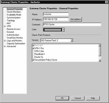
Figure 21.52: Defining General Properties of the Nokia Cluster
Particular areas of note here are that the IP address stated in the General tab is the external interface. The other important points to note are that the ClusterXL check box is unchecked.
Now click the Cluster Members menu option on the left side of this screen. Run through the steps for creating a new member, as we did when configuring Cluster XL HA New mode.
After the trust has been set up between the management module and enforcement module, click the Topology tab and click Get Topology. For each interface that is received, click it and set the topology for it. For example, the eth-s1p1c0 interface has IP address 195.166.16.131 assigned to it, and this is marked as our External interface in the topology. All the others are defined as This Network (see Figure 21.53).
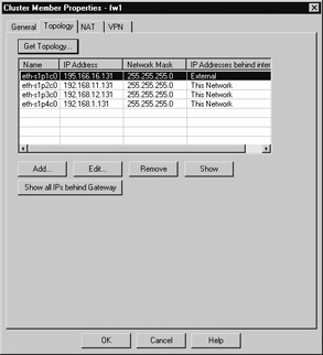
Figure 21.53: Topology of a Cluster Member
Click OK. You should now have the first member of the cluster defined and trusted. Repeat the procedure again in the Cluster Members menu to add the second cluster (and third, fourth, and so on). Use the New button each time. Once complete, you should have a list of cluster members defined.
Click Availability Mode on the left side of the screen to select which mode the Nokia cluster will operate in. Make sure you select Load Sharing (see Figure 21.54). Note that in Nokia clustering, this setting has no functional effect, but it is useful to select the correct one so that when you look at it again, you know what mode you are operating your Nokia cluster in! It is also useful to avoid any confusion if you need to seek technical support.
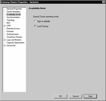
Figure 21.54: Availability Mode Configuration for a Nokia Cluster
Click the Synchronization menu option on the left side of the screen. You need to add the network you are going to use for synchronizing the FireWall-1 state tables. Note that this network should not be the same as your Nokia cluster control network.
Click the Add button to add a synchronization network. In our example, the IP address is 192.168.11.0 , and the netmask is 255.255.255.0. (See step 8 and Figure 21.23 of "Configuring ClusterXL in HA New Mode" for an example.) Click OK.
It is possible to add backup synchronization networks here; it would be acceptable to include the Nokia control network as a backup sync network, but if you do, the cluster should be monitored carefully so that a failover to this network is quickly identified and addressed.
Configuring topology in the cluster object when using Nokia clustering is not mandatory—in fact, it is not recommended. Doing so will change the behavior of the cluster with regard to packets originating from a member in the cluster. The effect of configuring a topology is covered in "Special Considerations for Nokia Clusters" later in this chapter.
Once this process is complete, you are ready to click OK and start defining your security policy.
Configuring the Nokia Cluster Rule Base
You have some choices as to the rule base you want to install. You can either see if the configuration of your cluster object is going to work and install an open policy, or you can create a strict policy now. Remember, there is still one more step to do, which is to configure the clustering on Nokia using Voyager. This being the case, you might want to install an open policy now and then tighten it later once you are happy that your clustering is working correctly.
You need to allow IPSO cluster control protocols between each IP address of the Nokia cluster. This means you will have a rule, close to the top of your rule base, that will look something like Figure 21.55.
![]()
Figure 21.55: Rule Showing Communication between Cluster Members
The group fwcluster-clusterips is made up of node host objects, one for each VIP address (195.166.16.130, 192.168.12.130, and 192.168.1.130 in our example).
| Warning | It is vital to add the fwcluster-clusterips group to security policy rules wherever you use the cluster object as a destination. This is because the cluster object does not include the VIP addresses, since we have not defined the cluster topology information. However, it is possible to connect to the VIP addresses. This is most important when defining the "stealth" rule (see Figure 21.57). |
The ipso-cc group is made up of two services that we will call IPSO Cluster Control Protocol 1 and IPSO Cluster Control Protocol 2. You define these by clicking Manage | Services | New | TCP. The definition of these services is shown in Figures 6.56 and 6.57, respectively.
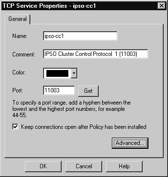
Figure 21.56: Defining Service for IPSO Cluster Control Protocol 1
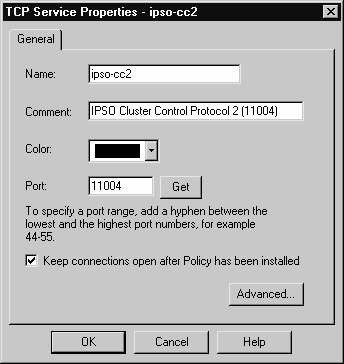
Figure 21.57: Defining Service for IPSO Cluster Control Protocol 2
Once defined, these services can be added to a service group (defined as ipso-cc in our example).
In addition to the ipso-cc services, we have also accepted the Network Time Protocol (NTP). Running NTP is a good idea to make sure that the time between the Nokia cluster members does not drift.
When you define the "stealth" rule in order to explicitly protect the cluster members, add the cluster object and the group of VIPs, fwcluster-clusterips, as shown in Figure 21.58.
![]()
Figure 21.58: A Stealth Rule on a Nokia Cluster Rule Base
Once you have configured your policy, install it to the cluster object. Note that in Figure 21.59, we can see that the policy will fail to install if it does not install to all members of the cluster. One thing to be acutely aware of here is that if a member in the cluster is down or switched off and later comes online and becomes functional, it will first look at other members of the cluster to compare the policy that it has against the policy that the other cluster members have. If the other cluster members have a more recent policy, the cluster member that has just come up will download the policy from one of the other cluster members—before it attempts to download the policy from the management module.
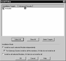
Figure 21.59: Installing the Security Policy for the Cluster
Once you have installed a policy, you have to complete the last step in configuring a Nokia load-sharing cluster: configuring the clustering on the Nokia appliances themselves.
Nokia Cluster Configuration on Voyager
When we configured the Gateway Cluster object in the SmartDashboard GUI, we did not configure the gateway cluster to have ClusterXL installed. This feature is not available on the Nokia platform; Nokia provides its own solution for load sharing. However, you have to configure it within the Voyager interface.
Note that you have to configure the cluster on each Nokia in the cluster, so you will have to repeat the procedure of configuring the cluster on each Nokia. This might sound obvious, but it is often something that is forgotten!
Voyager Configuration
Make sure that you have network connectivity from your browser to your Nokia FireWall-1 modules in your cluster, and make sure that the security policy you have installed on the Nokia appliances does not prevent you from accessing Voyager from your browser. Navigate to Voyager on the first member in your cluster. In our example, we do this by going to https://195.166.16.131 (see Figure 21.60).
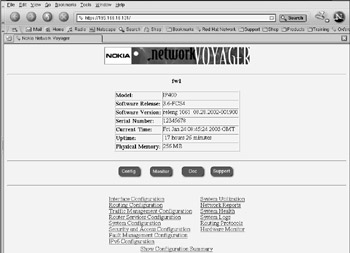
Figure 21.60: Voyager's Main Screen
Here are the steps you need to follow after you have authenticated and are presented with the main screen:
-
From the main Voyager screen, click Traffic Management Configuration.
-
Click Cluster. The new screen will look something like Figure 21.61.
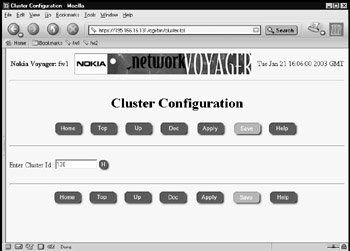
Figure 21.61: The Initial Cluster Configuration Screen -
Enter a cluster ID. This can be any decimal number between 0 and 65,535. For simplicity, we chose 130 for our example. Once you've entered an ID, click Apply and then Save.
-
The cluster configuration screen will then expand to include more parameters that can be configured within the cluster.
-
The bottom half of the screen presented in Figure 21.62 is shown in Figure 21.63; it shows how to configure the clustering for member fw1 in our example.
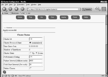
Figure 21.62: Uninitialized Cluster in Voyager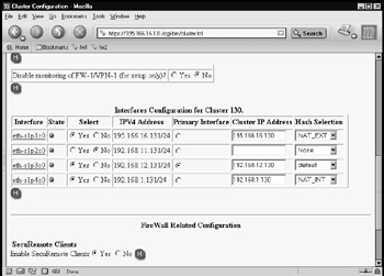
Figure 21.63: Cluster Configuration for the First Cluster Member -
Set up your cluster information. Note that the sync interface, eth-s1p2c0, has parameter No for the Select column and the Hash Selection column has None. The external interface eth-s1p1c0 has the hash algorithm NAT_EXT selected, and the internal interface eth-s1p4c0 has NAT_INT selected. The Cluster Control network has the Primary Interface option button checked, and the hash selection is set to default.
-
Decide if you are going to use SecuRemote Clients and select yes or no. If you scroll further down the screen, you will see a section for defining VPN tunnel information. This is where you enter the remote encryption domain and remote gateway IP address so that this information is taken into account when the load-sharing algorithm is calculated. This ensures that the same member of the cluster participates in the VPN connection (as asymmetric routing would cause the VPN to fail).
Warning UDP encapsulation for secure remote connections is not taken into account for the Nokia IPSO cluster load-sharing algorithm, so it will therefore fail.
-
Make sure that you click Apply and Save to save the changes you have made.
-
You can now make the cluster active, even with just one member. Click the Cluster State Up option button, and then click Apply and Save, as shown in Figure 21.64. Once it is up and running, your cluster should route traffic through member fw1, if adjacent hosts are using the VIP address of the local subnet that they are connected to as their default gateway.
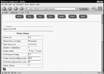
Figure 21.64: Bringing Up the First Cluster Member -
This completes member fw1 in the cluster configuration. You now need to point your browser to the second member and configure it to complement your configuration of member fw1. Note that the settings have to be correct and you have to use the equivalent interfaces on fw2 as fw1 and that the hashing algorithm you select must be identical to member fw1. When you change the Cluster State to Up, Voyager will inform you that the fw2 member is joining the cluster. This could take a little while (see Figure 21.65) and you will be informed as to whether the procedure succeeds or fails.
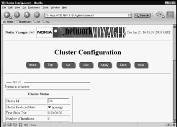
Figure 21.65: Member fw2 Joining the Cluster -
If joining the cluster is successful, the member will announce that it is now a member of the cluster (see Figure 21.66). Both members of the cluster are now up and running, and you are ready to test your Nokia cluster.
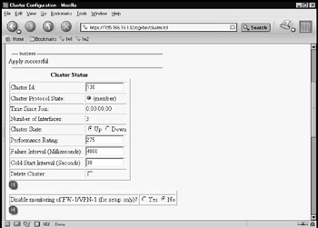
Figure 21.66: Second Member of a Nokia Cluster Is Now Online
Testing the Nokia Cluster
Once your Nokia cluster is set up, you need to test it to make sure that it is functioning correctly. Again, you need to keep in mind the way that this particular clustering technology works and how it differs from the other clustering solutions we have covered so far.
Test 1: Pinging the Virtual IP Address of Each Interface
With Nokia clustering in load sharing, you should be able to ping the local VIP address of the cluster with a host that is on the same subnet as the cluster interfaces. You will receive a response if everything is working properly.
In the test we ran on our example network, a ping was initiated from the FireWall-1 management station (195.166.16.134) to the VIP of the cluster (195.166.16.130). A packet trace was run at the same time on the management station to analyze the packet for the ping session. If you look at the ARP cache of the local host initiating the ping, you should now have the multicast MAC address of the VIP. In our case, this is 01:50:5a:a6:10:82 (which you can check against Figure 21.51). This in itself does not tell you much—just that the VIP address is up and running and that a member in the cluster responded. But can we tell which member?
The answer is yes, we can, but only if we examine the packet trace we took when the ping session took place. If we look at the reply packet, in the data link layer, we can see the real MAC address of the member that responded, as shown in the packet analysis in Figure 21.67.
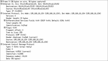
Figure 21.67: Analyzing the ICMP Echo Reply for the Source MAC Address
In our example, we can see that the source MAC is 00:0c:95:e2:b1:40, which corresponds with member fw2 in the cluster (see Figure 21.51). Note that even though the real MAC address of the fw2 member was used, the source IP address for the ICMP echo reply was the virtual IP of 195.166.16.130.
Test 2: Determining the Status of Each Member in the Cluster
In a Nokia cluster, there are two tools you can use to monitor the status of the cluster and its members. One is the SmartView Status GUI, and the other is using Voyager monitoring.
The SmartView Status GUI shows you the health of each member and if it is in state table sync with other members of the cluster. What it won't show you is the correct status of each interface of each member. For this information, you have to use the Nokia Voyager screens on each member in the cluster.
Notice that in Figure 21.68, all the interfaces seem to be up; however, they would report this status even if one of the interfaces was unplugged. The giveaway that SmartView Status cannot monitor the interfaces is that the "Working mode" field says Sync only. This means that the only function ClusterXL is performing on a Nokia cluster is state table synchronization.
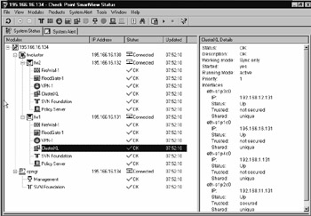
Figure 21.68: SmartView Status Does Not Show an Accurate Interface Status
Checking the monitoring of the cluster through Voyager is straightforward. Connect your browser to one of the members, select the Monitor button, and then click Cluster Monitor. This will show you the main statistics of each member in the cluster (see Figure 21.69) from the point of view of the member you are connected to. If everything is working correctly, it should not matter which member you connect to with Voyager, because they should all report the same status.
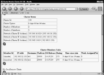
Figure 21.69: Both Members Are Online as Part of the Cluster
If a member in the cluster fails, you will see it removed from the cluster members table. If you only have one member left after a member fails (if you have a two-member cluster), the remaining member will also become master. Take note of the Time Since Join parameter in the cluster members table. This parameter tells you how long a particular member has been online.
One other place not to be forgotten when you're checking the health of your Nokia cluster is the system logs. These can be located in the /var/log/messages file. You should see entries from the clusterd process, which shows the status of the cluster.
In Figure 21.70, you can see a sample message of what will be seen in the /var/adm/message file when the internal Ethernet interface cable is removed from one of the members of the cluster, and then restored. Note that when this happens, you will also see the cluster members table show one fewer member in the cluster (see Figure 21.71).
Jan 27 07:29:35 fw1 [LOG_NOTICE] clusterd[251]: Member(192.168.12.132) member id (2) left cluster(130): Jan 27 07:30:15 fw1 [LOG_NOTICE] clusterd[251]: New member(192.168.12.132) joined cluster(130) with member id(2).
Figure 21.70: Sample of Nokia /var/log/messages After Internal Interface Was Removed, Then Restored
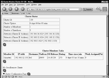
Figure 21.71: One Member Only in Cluster
Test 3: FTPing through a Load-Sharing Nokia Cluster During Interface Failure
Like ClusterXL load sharing and HA New mode, the best test you can perform is a real-world test. In load sharing, a simple test consists of starting a connection through the cluster and monitoring the cluster to determine which member the connection has gone through. If the test connection is the only connection, you might be able to see this from the "Work assigned" value in the cluster monitoring facility in Voyager, or you could use the FireWall-1 NG FP3 SmartView Tracker (with a hotfix applied to show origin IP addresses of the member in the cluster), or you could use SmartView Monitor.
In this example, we have started an FTP session through the cluster, and we are using SmartView Monitor to monitor the traffic through the cluster. When we initiate the FTP session through the cluster and start downloading data, we can see that all the load is on member fw2 in the cluster (see Figure 21.72).
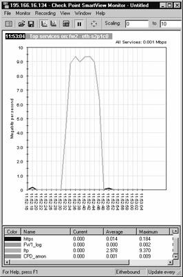
Figure 21.72: Display of Traffic through SmartView Monitor
As we can see in Figure 21.72, the FTP session was started at 11:52:30, and failure occurred at 11:52:48 (actually, we pulled the internal interface connector out of member fw2). Figure 21.73 shows that member fw1 took over the session.
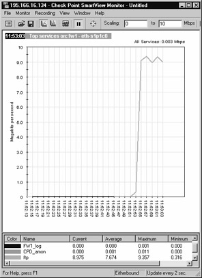
Figure 21.73: Display of Traffic through Member fw1 When fw2 Fails
Note that the timeline shows that member fw1 did not take over the load for three seconds.
Command-Line Stats
We saw earlier that ClusterXL uses the cphaprob command to determine status of the cluster. We can use a similar Nokia command-line tool to check the status of a Nokia cluster.
On the Nokia platform, we use the Command Line Interface Shell (known as clish). This is an interactive command line, although a single command can be executed using the –c "command" option. Once in the shell, you can use the command show clusters to determine the status of the members in the cluster (see Figure 21.74).
fw2[admin]# clish Nokia> show clusters CID 130 Cluster State up Member ID 1 Protocol State master System Uptime At Join 1:02:58:57 Performance Rating 275 Failure Interval 4000 Cold Start Delay 30 Number of Interfaces 3 Primary Interface eth-s2p3c0 Interface eth-s2p1c0 IP Address 195.166.16.132/24 Cluster IP Address 195.166.16.130 Hash NAT-external Interface eth-s2p3c0 IP Address 192.168.12.132/24 Cluster IP Address 192.168.12.130 Hash default Interface eth-s2p4c0 IP Address 192.168.1.132/24 Cluster IP Address 192.168.1.130 Hash NAT-internal Member(s) information Number of Member(s) 2 Member 1 (master) IP Address 192.168.12.132 HostName(Platform) fw2(IP400) OS Release 3.6-FCS4 Rating 275 Time Since Join 0:19:20:57 Cluster Uptime At Join 0:00:00:00 Work Assigned 50% Member 2 (member) IP Address 192.168.12.131 HostName(Platform) fw1(IP400) OS Release 3.6-FCS4 Rating 275 Time Since Join 0:19:14:34 Cluster Uptime At Join 0:00:06:22 Work Assigned 50% Nokia> show cluster securemote yes Nokia> show cluster vpn-tunnels VPN tunnel(s) configured Network/Mask Destination 192.168.254.0/24 194.155.13.33 Nokia> exit Goodbye..
Figure 21.74: Example of Use of the clish Command to Check the Cluster Status
Many commands are variations of the show cluster command. See the Nokia Command Line Reference Guide for further information. You can use the cphaprob command on the Nokia platform if you like, but the information that it will tell you is limited. For example, it can't tell you which interfaces are up or down. It can tell you if the state table synchronization is working or not.
How Nokia Clustering Works
Nokia clustering has many similarities to the Check Point ClusterXL load-sharing solution, but because the clustering is not part of the Check Point product, you do get some differences that are significant. We can draw some parallels between ClusterXL load sharing and Nokia clustering as follows:
-
Both ClusterXL load sharing and Nokia clustering use a VIP address and a multicast MAC address, so devices on the local subnet do not see any difference when initiating connections through the cluster. On a Nokia cluster, there is always a host that is assigned master in the cluster, and this member will respond to ARP requests.
-
Both ClusterXL and Nokia clustering have a method for each member to tell the other members its status in the cluster. However, the ways that they do this are different. ClusterXL does this using the CPHA protocol, which is sent from each interface of the cluster member to all other cluster members. Nokia uses a dedicated network to communicate using its own protocols: IP protocol 0x90 (144 decimal), which is a multicast MAC destination and IP address, and two TCP services (ports 11003 and 11004). Note that the protocol 0x90 traffic bypasses the firewall, so no policy rules are required.
-
Both systems have a load-sharing hashing method that can be altered by the user. On Nokia, this method is set up in Voyager, based on whether your interface is external or internal (or a VPN gateway); on Check Point ClusterXL, this is based on three choices: IP addresses, ports, and SPI (VPN negotiation); IP addresses and ports; or just IP addresses.
-
Like ClusterXL, connections through the Nokia cluster are directed through one member in the cluster on a per-connection basis. Asymmetric routing is avoided by the load-sharing algorithm, and although this would still work if it does occur, you could get some sessions dropped when they initiate, due to the reply being received from the remote host before the state tables have an opportunity to synchronize between the cluster members.
-
Just like ClusterXL, the Nokia members still have valid IP addresses that you can connect to.
Let's walk through an example of how a connection would work through a Nokia cluster. In our example, host 192.168.1.200 will initiate a Telnet session through the Nokia cluster to our ISP router on IP address 195.166.16.129, and as before, in our ClusterXL HA New mode, we will hide the connection behind the cluster external IP address of 195.166.16.130, using a hide rule in our firewall NAT rule base.
When the Telnet session is initiated, the host 192.168.1.200 sends out an ARP request for 192.168.1.130, which is the default gateway on the network 192.168.1.0. The response in the ARP will be a multicast MAC address—a MAC address that applies to all members of our cluster for the internal interface. The Nokia member that is the master will always send the ARP response. (More on the master later.) In our example, the MAC address returned is 01:50:5a:a8:01:82. Our host on 192.168.1.200 then sends a SYN TCP packet, high source port, destination is to 195.166.16.129, destination MAC is 01:50:5a:a8:01:82 (the default gateway MAC address).
All members in the cluster will receive this packet, but only one of them will do anything with the packet—depending on which member in the cluster is meant to pick up the packet, which is based on the load-sharing algorithm. The member who will deal with the connection will pass the packet up through the IP stack to the Check Point FireWall-1 NG FP3 kernel for the incoming interface. The TCP SYN packet will pass through the rule base of the firewall and, providing everything is fine, it will then send the packet out of its external interface, with the source IP address of 195.166.16.130 (the external cluster IP address), with the source MAC address of the member that is taking the connection (in our example, the source MAC address is 00:c0:95:e2:b1:40, which corresponds with member fw2 external interface eth-s2p1c0), and the destination IP address will be 195.166.16.129 (see Figure 21.75).
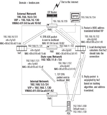
Figure 21.75: Description of a Connection through a Nokia Load-Sharing Cluster
If the Telnet daemon is listening when the packet reaches the ISP router on 195.166.16.129, it will produce a response. Again, the ISP router will issue an ARP request for IP address 195.166.16.130, which is the VIP of the cluster. The master member will respond to the ARP request, sending the multicast MAC address as the MAC address associated with IP 195.166.16.130 (but it will keep the source MAC address of the ARP reply as its own physical external interface; this is one way to see which of your Nokia members is the master without using Voyager). Host 195.166.16.130 will then send a SYN,ACK TCP packet, the source IP will be 195.166.16.129, source port will be 23, and the destination MAC will be the multicast MAC address of the VIP 195,166.16.130, which is 01:50:5a:a6:10:82 in our example.
Again, the reply packet gets onto all members in the cluster, and the correct member that took the original SYN packet for the connection is selected by the hashing algorithm that was selected for that interface.
| Note | It is important to understand the importance and meaning of the various hashing algorithms. The reply packets get sent back through the same member based on which hashing algorithms you select. For example, if you use Hide NAT when initiating a connection that leaves through the external interface, you have to pick hashing methods that take the NAT into account: NAT_EXT for the external interface, NAT_INT for the internal interface. Not doing this could cause the reply packets to be accepted by the wrong member in the cluster by the load-sharing algorithm, ending up with asymmetric routing. In some complex NAT configurations, there will be conflicts as to which hashing algorithms should be used—for example, where "double NAT" takes place. If these configurations cannot be avoided, other measures should be taken to avoid asynchronous routing, such as static routing via members. This could well lead to imbalances in load sharing and lack of resilience for some connections. |
The packet then leaves the internal interface of member fw2 in our example; the source IP is the 195.166.16.129 IP address of the ISP router, the source MAC address is the internal interface MAC address 00:c0:95:e2:b1:43 of fw2, and the destination IP is now 192.168.1.200 (it has been address translated by FireWall-1).
Nokia Cluster Failover
In the event of a failure condition, network traffic taken by that member needs to be routed by an alternative member in the cluster. This is done on the cluster control network. Again, the key is the cluster control protocol that uses this network.
The Nokia cluster control protocol is used by the member that is the master. The master member sends out the status of the cluster to all other members in the cluster, using the cluster control protocol. The master member is usually the first member that is made active when you create a Nokia cluster. If the master fails, another member will take over and become master. There is only one master member in any cluster, but the member that is master can change depending on failures in the cluster.
When the master member in the cluster communicates with the other members in the cluster, it uses the Nokia cluster control protocol, which is IP protocol 0x90 (144 decimal). The cluster control network is used exclusively (unlike the CPHA protocol used in ClusterXL). When the master communicates with the other members in the cluster, it is from the real source MAC address of the master on the control network, the source is the real IP address of the master, the destination MAC address is a multicast MAC address, and the IP address is a multicast IP address. For example, if member fw1 were the master, it would send out a packet, source MAC 00:c0:95:e0:15:de, source IP 192.168.12.131, destination MAC 01:00:5e:00:01:90, destination IP address 224.0.1.144. All members that receive the packet will often respond, with their real source MAC and IP address, to the real destination MAC and IP address of the master.
In our example, if member fw1 were the master and member fw1 failed, fw2 would be the master. You would notice that fw2 would start to issue IP protocol 0x90 packets from its real IP, and the destination IP would be the multicast IP for the other members in the cluster. This is another method you can use to determine which member in the Nokia cluster thinks it is the master. Note that when a new master is chosen, it will stay the master until it fails and cannot be the master any longer. You will also see TCP ports 11003 and 11004 Nokia cluster control connections on the cluster control network.
Failover from the point of view of the networking devices on the same local subnet as the VIPs is transparent because the MAC address used by the cluster does not change. There will be a short delay during failover as the load-sharing algorithm determines which member in the cluster will take over the connections of the failed member. This process can take up to four seconds.
Nokia Failover Conditions
Failure of a Nokia cluster member is determined when one of the following occurs:
-
IP forwarding fails or is stopped (for example, by cpstop).
-
The FireWall-1 process fwd dies.
-
An interface goes down.
All these scenarios are monitored by the clusterd process on each Nokia member. When a failover occurs, the clusterd process logs the event in the Nokia system logs (/var/log/messages file).
Special Considerations for Nokia Clusters
We have talked a little about how the Nokia clustering solution works, so based on how the technology in Nokia clustering works, we need to take into account its effects when setting up our cluster and the rule base we are likely to use.
Network Address Translation
As with all clusters, the way you decide to implement your NAT rules needs to be taken into account. In ClusterXL in HA New mode, we noticed that you cannot use manual proxy ARP entries into the OS. In ClusterXL in Load-Sharing mode, we stated that all methods of NAT and proxy ARP should work fine.
In a Nokia cluster, you cannot use Check Point's own Automatic ARP setting in the Policy | Global Properties | NAT – Network Address Translation | Automatic Rules for Automatic ARP Configuration menu.
The reason for this is that each member will proxy ARP for the real MAC address of the member in the cluster as opposed to proxy ARPing the multicast MAC address of the cluster. For this reason, you cannot use Automatic ARP Configuration.
You can enter proxy ARP entries into Voyager for NATed IP addresses, using the multicast MAC address of the cluster interface. You can also use static routes on the ISP router to route traffic to the VIP address of the cluster for the NATed IP address.
If you plan to use proxy ARPs for multicast MAC addresses on the Nokia platform, you need to enable Accept Multicast reply to ARP on the ARP page of the Voyager interface. You need to do this for all members that make up your cluster.
| Note | Accept Multicast reply to ARP must be enabled for the cluster to work properly. |
Defining the Cluster Object Topology
When defining the gateway cluster object for the Nokia cluster, it is possible to define the cluster topology, listing the VIPs. However, this apparently harmless change results in a significant change in FireWall-1 behavior. Connections that originate from individual cluster members are subject to implicit Hide NAT behind the outgoing cluster VIP. This will affect traffic such as DNS lookups and outgoing FTP connections originating from cluster members. This is the same behavior we saw under ClusterXL. As with ClusterXL, once FP3 Hot Fix 1 is applied, packets routed back to the wrong member will be routed onward via the sync link. Check Point ClusterXL makes allowances for this when handling this traffic, dealing with it gracefully. A Nokia clustering solution will not deal with it as well, and the traffic involved will not be reliable. This behavior will also cause a problem with traffic between external interfaces of members. For these reasons, defining the cluster topology is not recommended when you're using a Nokia solution. Possibly this configuration will be made workable in future releases of NG.
|
EAN: 2147483647
Pages: 240