Section 4.5. Error Detection and Correction
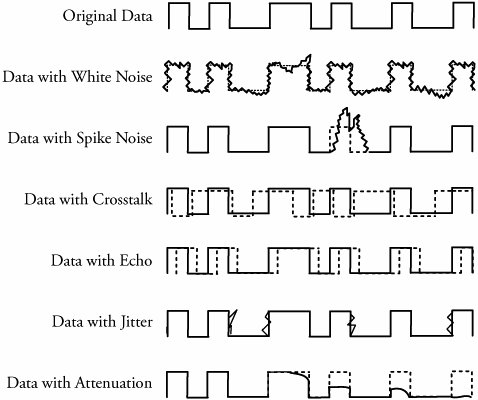
4.5. Error Detection and CorrectionError sources are present when data is transmitted over a medium. Even if all possible error-reducing measures are used during the transmission, an error invariably creeps in and begins to disrupt data transmission. Any computer or communication network must deliver accurate messages. Error detection is applied mostly in the data-link layer but is also performed in other layers . In some cases, the transport layer includes some sort of error-detection scheme. When a packet arrives at the destination, the destination may extract an error-checking code from the transport header and perform error detection. Sometimes, network-layer protocols apply an error-detection code in the network-layer header. In this case, the error detection is performed only on the IP header, not on the data field. At the application layer, some type of error check, such as detecting lost packets, may also be possible. But the most common place to have errors is still the data-link layer. Possible and common forms of errors at this level are described here and are shown in Figure 4.5. Figure 4.5. Common forms of data errors at the data-link level
No link is immune to errors. Twisted-pair copper -based media are plagued by many types of interference and noise. Satellite, microwave, and radio networks are also prone to noise, interference and cross talk. Fiber- optic cable too may receive errors, although the probability is very low. 4.5.1. Error Detection MethodsMost networking equipment at the data-link layer inserts some type of error-detection code. When a frame arrives at the next hop in the transmission sequence, the receiving hop extracts the error-detection code and applies it to the frame. When an error is detected , the message is normally discarded. In this case, the sender of the erroneous message is notified, and the message is sent again. However, in real-time applications, it is not possible to resend messages. The most common approaches to error detection are
The parity check method involves counting all the 1 bits in the data and adding one extra bit, called the parity bit . This makes the total number of 1 bits even (even parity) or odd (odd parity). The parity-check method is the simplest error-detection technique but is not effective. The cyclic redundancy check (CRC) method is one of the most elaborate and practical techniques but is more complex, adding 8 to 32 check bits of error-detection code to a block of data. Our emphasis is CRC. At this point, we need to clarify that the Internet checksum is another error-detection method, though it is used at the network and transport layers and is discussed in Chapters 7 and 8. 4.5.2. Cyclic Redundancy Check (CRC) AlgorithmThe cyclic redundancy check (CRC) method provides smart error checking and has been adopted in most computer and communication systems. Figure 4.6 shows error detection and correction on links, using CRC for a transmitter. Figure 4.6. Error detection on links using the CRC method at a transmitter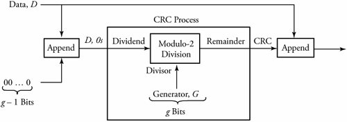 In any system, a standard and common value between transmitters and receivers is adopted for error processing. This g -bit-long value, known as a checking generator , is denoted by G . At the transmitter, a partial or entire packet or frame is treated as a block of data, and each block is processed individually. The CRC algorithm at the transmitter part can be summarized as follows . Begin CRC Algorithm at Transmitter
At the other end point of the communication system, the receiver receives the value of D , CRC and performs the following algorithm to detect errors, as shown in Figure 4.7. Figure 4.7. Error detection on links, using CRC at a receiver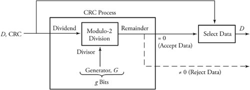 Begin CRC Algorithm at Receiver
The modulo-2 division arithmetic is very simple. A modulo-2 division function is done without carries in additions or borrows in subtractions . Interestingly, the module-2 division function performs exactly lke the Exclusive-OR logic. For example, with modulo-2 arithmetic, we get 1 + 1 = 0 and 0 - 1 = 1. Equivalently, with logic Exclusive-OR: 1
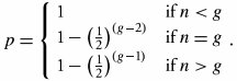
The CRC algorithms are fairly straightforward. Consider again the example. A fact from the modulo-2 arithmetic states that the remainder is always ( g - 1) bits long; therefore, for this example, the remainder is 4 bits long. Hence, if we make sure that g - 1 additional 0s, or four 0s in the example, are at the end of the dividend, the receiver can perform an identical arithmetic in terms of size of dividend. If the transmitter produces a remainder, let's say 1,000, the addition of this value to the same data can indeed result in 0 remainder, provided that the data is the same data used in the transmitter. Therefore, if there is any error during transmission, the remainder may not become 0 at the receiver, giving a notion of error. Equivalent Polynomial InterpretationThe preceeding analogy can be restated such that the CRC error-detection method treats the data to be transmitted as a polynomial. In general, consider the bit string a n -1 a n -2 a n -3 ... a , which forms a generic polynomial: a n -1 x n -1 + a n -2 x n -2 + a n -3 x n -3 +...+ a x , where a i can be 0 or 1. In other words, when a data bit is 1, the corresponding polynomial term is included. For example, the bit string D = 1010111 produces the string a 6 a 5 a 4 a 3 a 2 a 1 a = 1010111, which is interpreted as x 6 + x 4 + x 2 + x 1 + x . The generator value, acting as the divisor, is known as the generating polynomial in this case. Some well-known and widespread industry-approved generating polynomials common divisor between transmitters and receiversused to create the cyclic checksum remainder are: CRC-8 for ATM: x 8 + x 2 + x + 1 CRC-12: x 12 + x 11 + x 3 + x 2 + x + 1 CRC-16: x 16 + x 15 + x 2 + 1 CRC-CCITT: x 16 + x 15 + x 5 + 1 CRC-32 used in IEEE 802: x 32 + x 26 + x 23 + x 22 + x 10 + x 8 + x 7 + x 5 + x 4 + x 2 + x + 1 Note that the polynomial interpretation is simply a convenient method of explaining the CRC algorithm. In practice, the transmitter and the receiver perform divisions in bits, as described earlier. Effectiveness of CRC The CRC method is pretty goof-proof. However, an analysis is needed to answer whether the receiver is always able to detect a damaged frame. Consider the generating polynomial x g -1 + x g -2 + ... + 1 with g terms. Apparently, g - 1 is the highest power of the generating polynomial. Let n be the length of burst error occurring in a received message. If the size of the error burst is n<g , error detection is 100 percent. For all other cases, the terms between x g -1 and 1 define which bits are erroneous. Since there are g - 2 such terms, there are 2 g -2 possible combinations of erroneous bits. Considering that all combinations can occur with equal probability, there is a chance of Equation 4.10
which is close to 1. Implementation of the CRC Process UnitHardware with a combination of software performs the process of division very quickly. An example of the basic hardware used to perform the CRC calculation is shown in Figure 4.9. The hardware includes a simple register that implements the CRC process-generating polynomial x 4 + x + 1. Except for the first term ( x 4 ), an Exclusive-OR is included for each power of existing term, as shown. Note that the notion of the generator value 10010 is now appearing in the form of hardware shown by a combination of 1-bit shift registers and Exclusive-OR gates. Therefore, we can see from the figure where there is a term in the generating polynomial. Figure 4.9. CRC process: The most significant bit enters first.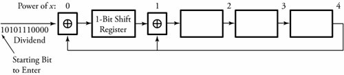 Initially, the registers contain 0s. All data bits of 1010111, 0000 , beginning from the most-significant bit, arrive from the left, and a 1-bit shift register shifts the bits to the right every time a new bit is entered. The rightmost bit in a register feeds back around at select points. At these points, the value of this feedback bit is Exclusive-ORed, with the bits shifting left in the register. Before a bit shifts right, if there is an Exclusive-OR to shift through, the rightmost bit currently stored in the shift register wraps around and is Exclusive-ORed with the moving bit. Once all data bits are fed through, the register's contents must be exactly the same as the remainder indicated in Figure 4.8 (a). |
 1 = 0, and 0
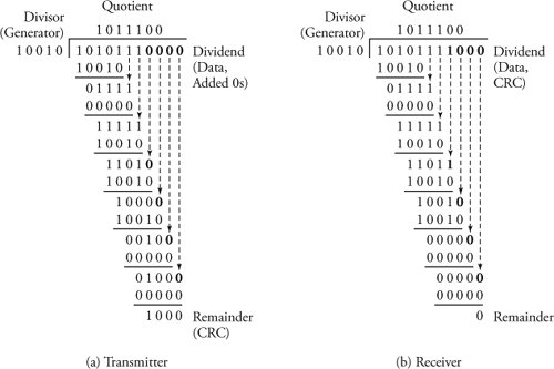
EAN: 2147483647
Pages: 211