Section 14.6. Case Study: An All-Optical Switch
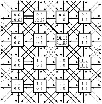
14.6. Case Study: An All-Optical SwitchAs a case study on optical switching networks, we consider the spherical switching network (SSN), a switch fabric first introduced by the author of this book in the Journal of Computer Networks (issue 40, 2002). The spherical network is a regular mesh network that can be realized as a collection of horizontal, vertical, and diagonal rings, as shown in Figure 14.11. Rings appear in bidirectional pairs that can form cyclical entities and create full regularity in the structure of the network. The spherical network uses a simple self-routing scheme. Furthermore, the availability of a large number of interconnections among switch elements and the special arrangement of interconnections potentially reduce the number of deflections compared to the existing deflection -routing networks. Figure 14.11. A 16-port proposed spherical switching network. Each square represents a 9 x 9 switch element with eight pairs of internal links (shown) and one pair of external links (not shown). An example for self-routing is from switch element 0000 to 1011. The network is constructed with fixed- size switch elements, regardless of the size of the network. Each switch element consists of a 9 x 9 crossbar and a local controller. Although not indicated in the figure, an incoming link and an outgoing link connect the network at each switch element to external links and then to local processors, which deliver and receive data sent through the network. One of the nine pairs of links is external and carries the external traffic; the other eight pairs are internal. The spherical network doesn't use any buffering within the network, and thus this network gains from the lower complexity when compared later with other switching networks. Contention resolution in each switch element is based on the deflection of losing packets on undesired internal links and with increments in their priority fields. With the torus -shaped topology embedded in the network, when more than one packet requests the same outgoing link at each switch element, only one of them is forwarded on the preferred link; the others are deflected onto other links. By maintaining this rule in the system, once a packet is admitted to a network, it is not discarded when congestion occurs. Instead, the packet receives an increment in its priority field and is misrouted temporarily but will reach its destination. One main advantage of this network over many others is the existence of possible multiple equally desired outputs at each switch element. In other words, it might be possible at each point in the network to find more than one shortest path to a destination. 14.6.1. Self-Routing in SSNThe routing in the spherical network is fairly simple and is self-routing. Any switch element is given an index number. For example, the indices in a 16-port network are [00 - 00] through [11 - 11], as in Figure 14.11. Depending on whether the flowing traffic is directed toward decreasing index or increasing index, the self-routing is performed by decremental or incremental addressing, respectively. Clearly, the network has four routing cases:
In each case, there are a certain number of shortest paths through which a packet is channeled to its destination by taking a corresponding direction. In the first case, depending on whether the index number of the source is greater or smaller than the index number of the destination, the value of the second two index bits of the source address is decreased or increased hop by hop, respectively, until the address of a source and a destination becomes identical where the routing is completed. In the second case, the process is identical to the horizontal case but in a vertical direction, and index decrement or increment is done on the value of the first two index bits of the source address. In case 3, the routing process is accomplished when the values of both the first and second two index bits of the source address simultaneously receive increment or decrement, as described in cases 1 and 2. Case 4 can be a combination of either the first and third cases or the second and third cases. In case 4, there might be more than one preferred path. The preceding routing rules use the preferred directions to route each packet to its destination along a shortest path. Contention resolution in each switch element is based on deflection of a losing packet onto an undesired output if all preferred outputs are not available and giving an increment to the priority field of the packet. 14.6.2. Transmission in SSNSSN can be used to construct an all-optical switch core . Suppose that any optical signal is assigned a unique wavelength. To use the fiber bandwidth efficiently , it is divided into 72 nonoverlapping optical wavelengths corresponding to 8 + 1 pairs of links at each switch element. Each node is connected into eight other nodes through eight pairs of internal optical links plus a pair of external links. There are nine groups of wavelengths : (1),(2), (3), (4), (5), (6), (7), (8), and (9). Each group of wavelengths includes eight nonoverlapping optical wavelengths:
Wavelength groups (1) through (8) are assigned to the eight pairs of internal links, and (9) is assigned to the external links. At each incoming fiber link, there are at most eight packets multiplexed into one fiber. All packets are destined to different addresses. When packets arrive at a node, they are demultiplexed, and the node makes the routing decision for each packet. After a next hop for each incoming packet is decided, the wavelength of that packet is converted to one of the available wavelengths by wavelength converter and is then transmitted to the next switch element. |
EAN: 2147483647
Pages: 211