Section 14.4. Optical Routers
14.4. Optical RoutersAn optical router , known as the wavelength router , or simply a network node , is a device that directs an input wavelength to a specified output port. Each router in a network is thus considered a node. Optical nodes are classified as either broadcast nodes or wavelength routing nodes . In a broadcast node, a wavelength is broadcast by a passive device to all nodes. The passive device can be an optical star coupler . A coupler combines all incoming signals and delivers a fraction of the power from each signal on to each output port. A tunable optical filter can then select the desired wavelength for reception . Broadcast nodes are simple and suitable for use in access networks, mainly LANs. The number of optical links connected to a broadcast node is limited, since the wavelengths cannot be reused in the network. Wavelength routing nodes are more practical. Figure 14.6 shows an overview of an n x n wavelength routing node in which full connectivity is ensured between n inputs and n outputs, using m wavelengths. In general, a signal with wavelength i arriving at input j of the router denoted by » i,j can be switched on any of the n output ports. For example, a light with wavelength » 3,2 among all wavelengths {» 1,2 , » 2,2 , » 3,2 , ..., » m,2 } arrives on the second input port of the router. This wavelength can be switched on any of the outputs and, possibly, with a different wavelength, as » 4,7 . Figure 14.6. Overview of a wavelength routing node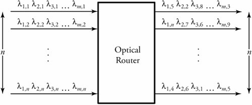 14.4.1. Structure of Wavelength Routing NodesWavelength routers are of two types. The first type can switch an input only to an output using the same wavelength. Figure 14.7 gives an overview of this router. Consider this router with n inputs and n outputs, where each input i can bring up to m wavelengths as { » 1, i » 2, i , » 3, i , ..., » m,i }. In this case, any wavelength » k, i can be switched on output j with wavelength » k,j . This way, in each round of switching, all wavelengths at the input ports with the same wavelengths can be switched to desired output ports taking place in the same corresponding channels. As shown in Figure 14.7, the router consists of n input WDMs, m optical switches of size n x n , and n output WDMs. Figure 14.7. An all-optical router that replaces wavelength channels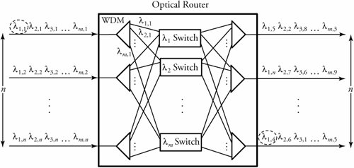 The second type of wavelength router requires wavelength-conversion capabilities, as illustrated in Figure 14.8. Consider this router with n inputs and n outputs with up to m wavelengths per input. With this router, a wavelength » k,i at input i can be switched on output port j ; in addition, the k th wavelength can be converted to the g th, to be shown by » g,j . This way, in each round of switching, any wavelength at the input port with the same wavelengths can be switched on any output port, using any available wavelength. In Figure 14.8, » 2,1 from input 1 is switched to » 1,4 on the n th output. Figure 14.8. An all-optical router, which can replace wavelength channels and convert wavelengths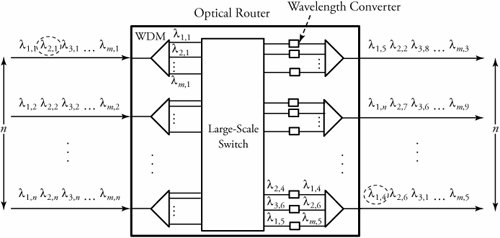 In general, wavelengths may be required to be converted in a network for the following reasons:
Depending on whether a wavelength converter converts a fixed- or variable-input wavelength to a fixed- or variable-output wavelength, there are different categories for wavelength converters, such as fixed-input fixed-output, fixed-input variable-output, variable-input fixed-output, and variable-input variable-output. Semi-Optical RoutersDepending on the type of a switch fabric used in the structure of an optical router, we can further classify optical routers into two main groups:
All-optical , or photonic , switches , are the ones we have studied so far. In such switches, the optical signal need not be converted to electrical, and switching is handled in the optical domain. All-optical domains have an advantage of large-capacity switching capabilities. In the optically opaque, or so-called semioptical switches, an optical signal is converted to electrical, and then the appropriate switching takes place. It is obviously a case with an electrical switch core followed up with optical interfaces. In an all-optical switch, switching and wavelength conversion take place entirely in the optical domain. An optically opaque switch uses an optoelectronic conversion mechanism. This architecture requires other interfaces, such as optical-to-electrical converters or electrical-to-optical converters. The electronic segments are used around the optical switch matrix. |
EAN: 2147483647
Pages: 211
- Chapter II Information Search on the Internet: A Causal Model
- Chapter III Two Models of Online Patronage: Why Do Consumers Shop on the Internet?
- Chapter V Consumer Complaint Behavior in the Online Environment
- Chapter VII Objective and Perceived Complexity and Their Impacts on Internet Communication
- Chapter XV Customer Trust in Online Commerce