Section 13.5. Concentration and Expansion Switches
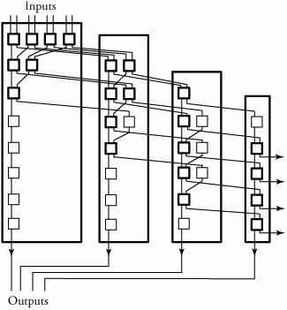
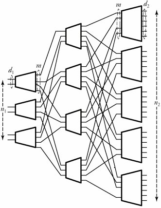
13.5. Concentration and Expansion SwitchesThis section introduces switching networks that either expand or concentrate incoming traffic. In a concentration-based switching network, the number of output ports is less than the number of input ports. In an expansion-based switching network, the number of output ports is more than the number of input ports. 13.5.1. Knockout Switching NetworkOne of the simplest concentration switching networks is called a knockout switch , shown in Figure 13.9. The knockout switch is a blocking network and is constructed with interconnected crossbars with less complexity than a crossbar switch of the same size . The knockout switch is a good substitution for a crossbar switch when the likelihood is small that many inputs will need to send packets to the same output simultaneously . Figure 13.9. The knockout switching network The idea of this switch is based on the concept of knocking a possible k packets out of n active inputs if the number of switch outputs is m , where m < n . To implement this mechanism, consider the example illustrated in Figure 13.9, where n = 8 and m = 4. Assume that all the eight inputs have packets to transmit to outputs; obviously, the system would need to discard a minimum of four packets. The switching network consists of a number of either 2 x 2 switch elements and delay elements. The switch elements act as concentrators , ensuring fairness to all entering packets. The eight incoming packets from eight switch inputs compete in the first four switch elements. A packet that wins the competition, based on a random selection in a switch element, stays in the same column of switches and continues to reach its desired output. Otherwise, a losing packet is knocked out to the next column of switch elements for the next round of competition. Thus, the first-round losers in this process go straight to the second column and play off against one another and at later stages, face the second-and the third-round losing packets from the first column. Note that the system needs to ensure that no input port is singled out for bad treatment every time the output is overloaded. This fairness task is implemented by playing packets against one another in a form of a knockout column-by-column scenario to select m winners. In the second column, two packets, including those losing packets, are competing in a similar fashion to reach their desired outputs, and so on. Finally, all the losing packets are dropped, and eventually, we select up to m = 4 packets, dropping all the rest. Note that this process requires timing synchronization if all the incoming packets are to experience the same switching delay. To ensure packet time synchronization, the delay elements present units of delay to packets, as shown in the figure by additional delay units. 13.5.2. Expansion Network An expansion network with n 1 inputs and n 2 outputs, where n 1 < n 2 , can scale up the number of receivers from n 1 to n 2 . A three-stage expansion network is shown in Figure 13.10. This network is constructed with three types of crossbars of sizes d 1 x m , Equation 13.16 Figure 13.10. A three-stage expansion switching network An expansion network is a generalization of the three-stage Clos network and is useful in applications in which an incoming signal is to be sent to multiple outputs. Such networks are also called distribution networks . Considering the previous network dimensions, the complexity of a three-stage expansion network, X e , is derived by Equation 13.17 An expansion network is nonblocking if m
|
 (
( EAN: 2147483647
Pages: 211
- Machine Languages, Assembly Languages and High-Level Languages
- Formulating Algorithms: Sentinel-Controlled Repetition
- Formulating Algorithms: Nested Control Statements
- Case Study: Card Shuffling and Dealing Simulation
- (Optional) Software Engineering Case Study: Starting to Program the Classes of the ATM System