Cisco VPN 3002 Features
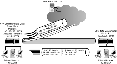
| As you recall from Chapter 3, "Cisco VPN 3000 Concentrator Hardware," the VPN 3002 client comes in two flavors. The CVPN 3002 model contains a single autosensing 10/100Mbps private interface and an autosensing 10/100Mbps public interface. The CVPN 3002-8E model contains a similar public interface; however, the private interface comprises an 8-port 10/100Mbps switch for multiple Ethernet device connectivity. Both models can function in two different operating modes and support pushed configurations and policies from the central location, as the following sections discuss. Client ModeThe hardware client runs in one of two operating modes. The simplest and default mode is known as Client mode (also called PAT mode). In this operating mode, the hardware client utilizes Port Address Translation (PAT) for its communications with the central concentrator. The VPN 3002 in Client mode emulates a single remote access client by requesting an internal tunnel IP address from the central concentrator. All devices behind the hardware client are isolated and hidden from the central location's network. This is possible because the IP addresses of traffic originating from the client's private network are translated to the hardware client's assigned internal IP address. Thus, devices on the central network see only traffic originating from the assigned tunnel IP address. With that being said, devices on the central network cannot initiate communications with stations behind the hardware client because they do not know the stations' actual IP address. PAT is also utilized when split tunneling is enabled from the central concentrator and devices behind the hardware client need to access resources on the Internet. In these instances, the private network behind the VPN 3002 Hardware Client is translated to the public IP address configured on the hardware client's public interface. Whether the traffic is destined for the tunnel or the Internet, the VPN 3002 maintains all translations in its NAT table so it knows where to forward traffic returned to that device. An illustration of the Client mode operation is shown in Figure 9.1. In this example, the VPN 3002 is operating in Client mode and has received an internal IP address of 10.1.1.113/24 from an IP pool configured on the central VPN Concentrator. When stations on the VPN 3002's private network (10.3.3.0/24) want to communicate with the VPN Concentrator's private network (10.2.2.0/24), the VPN 3002 Hardware Client utilizes PAT to translate the inside source address from the station's private IP address to the hardware client's assigned IP (10.1.1.113). Therefore, all stations on the VPN Concentrator's network receive packets from a single-source address and are unaware of the sending stations' private IP addresses. Because the traffic is destined for the remote network across the tunnel, the packet is encrypted using the ESP protocol and an additional ESP header is added to the protected packet for routability. All receivers of this traffic on the 10.2.2.0 network appear to be receiving the packets from the same source of 10.1.1.113. Also illustrated in the example, when users behind the hardware client access the Internet (such as www.examcram.com) through the split tunnel, the VPN 3002 translates the original source IP address to reflect the hardware client's IP address of the public interface (192.168.200.101). Figure 9.1. VPN 3002 Client mode operation.
Network Extension ModeNetwork Extension mode is a similar concept to LAN-to-LAN tunnels in the VPN 3000 Concentrator. In Network Extension mode (also called Tunnel mode), the VPN tunnel acts like a site-to-site bridge between the remote network and the central location's network. Unlike Client mode, Network Extension mode does not employ PAT for communications between the two networks. Without this PAT functionality, users behind the hardware client are visible to the central office's network. This end-to-end visibility is sometimes necessary for applications and services that are incompatible with PAT and require end-to-end IP traceability. In instances where split tunneling is enabled from the central concentrator, the VPN 3002 Hardware Client still utilizes PAT for traffic destined for the Internet. However, regardless of the enforced split tunneling policy, PAT is not utilized for inter-tunnel traffic in Network Extension mode. To utilize Network Extension mode, PAT must be disabled and the Private Interface's IP address must be changed from its default value. Additionally, Network Extension mode does not receive any IP assignments from the central concentrator.
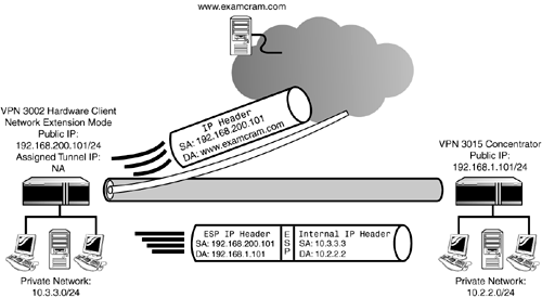
Demonstrated in Figure 9.2, Network Extension mode looks very similar to the Client mode example in Figure 9.1. However, a key difference between the two examples is that the inside tunnel address is not translated in Network Extension mode. This is represented in Figure 9.2 by the fact that the packet traversing the tunnel has an internal source address of 10.3.3.3, which is the actual private address of the sending station. As previously mentioned, when split tunneling is enabled, the VPN 3002 Hardware Client still utilizes PAT for outgoing packets to the Internet. In the example, when stations need to send clear text data to the Internet with split tunneling, the VPN 3002 performs PAT on the IP packets and translates the source IP address to the IP address of the public interface. Figure 9.2. VPN 3002 Network Extension mode operation.
Interactive Hardware Client AuthenticationBecause the hardware client is a client within itself, it requires a group and user account on the central VPN 3000 Concentrator just like individual software clients. When you initially configure the hardware client, you can input these authentication attributes so that it will initiate and maintain a tunnel when traffic demands it. To protect the central location from this automatic tunnel initiation (for example, if visitors use the remote's LAN), you can implement a function called Interactive Hardware Client Authentication. This feature is enabled from the central location's VPN Concentrator and is pushed down to the hardware clients that belong in that group. After it is enabled, connecting hosts behind the hardware client have to manually initiate the tunnel directly from the hardware client. When the tunnel request is initiated, the requesting host must authenticate the hardware client to the central concentrator with a valid username and password. After the tunnel is established, any subsequent devices on the LAN can utilize the tunnel until it disconnects. Individual User AuthenticationIndividual User Authentication is another centrally pushed feature that incorporates additional security measures. Namely, it requires all individual hosts behind the Cisco 3002 Hardware Client to authenticate to the VPN 3000 Concentrator by providing a valid username and password. After the individual host is authenticated by the central site, it can traverse the tunnel. Unlike Interactive authentication, this authentication feature is active whether or not the tunnel is already established. In fact, this utility can be implemented by itself or in conjunction with Interactive authentication. |
EAN: 2147483647
Pages: 185

