Top-Level Containers
The Mathematics of GUIs
Coordinate Systems
The art of creating a GUI is most certainly the art of illusion. When we press a button in a window with a mouse and see it “depress”, when we say that one window is hiding part of another because it is “in front of” the other, when we say than an icon is “transparent” because we can see what is “behind” it, we are willingly succumbing to this illusion. The GUI elements on the screen seem somehow tangible and we can hardly avoid thinking of them as “objects”, but it all boils down to nothing more than pixel coordinates and colors painted on a computer screen canvas. Therefore, it is appropriate to discuss the computer screen itself briefly from a GUI designer’s perspective.
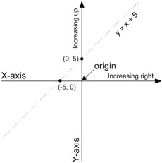
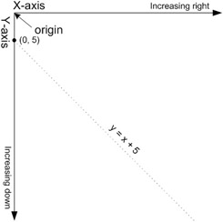
The computer screen can be thought of as a 2-dimensional Cartesian coordinate system with horizontal x-axis and vertical y-axis. The origin (x = 0, y = 0) is the top-left corner of the screen. Distances are measured in pixels with x-axis coordinates increasing rightwards and y-axis coordinates increasing downwards. Yes, downwards! This is at odds with what we all learned in Algebra 101, but it is natural for the computer which paints the screen pixel by pixel the same way we read a book: moving left to right and top to bottom. Take a moment to compare the difference between the standard mathematical coordinate system and the coordinate system of a computer screen. To help illustrate the difference, the line with equation y = x + 5 is graphed in both systems in Figures 12-1 and 12-2.

Figure 12-1: Standard Algebraic Coordinate System

Figure 12-2: Standard Computer-Screen Coordinate System
Components and Their Bounds
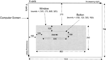
GUI components such as windows and buttons generally occupy rectangular areas, so their exact size and location can be given by the x- and y-coordinates of their top-left corner, their width and their height. Together, these four values define what is known as the bounds of a component. Just as the computer screen has a coordinate system, so do all GUI components. Every component considers its own top-left corner to be its local origin with x-coordinates increasing rightward and y-coordinates increasing downward. The bounds of a component are always expressed in terms of its container’s coordinate system. Figure 12-3 shows a window with bounds x = 100, y = 275, width = 600, height = 350. Its bounds are in screen coordinates because the screen contains the window. The “Click Me” button which is inside the window, has bounds x = 125, y = 125, width = 300, height = 100. Its bounds are in window coordinates because the window contains the button.

Figure 12-3: Components and Bounds
EAN: 2147483647
Pages: 452