Section 11.1. Internal Structure
11.1. Internal StructureChapter 5 introduced possession-related relationships between classes, including association ("has a") and composition ("contains a"). Composite structures offer an alternate way of showing these relationships; when you show the internal structure of a class, you draw the items it possesses directly inside the class. Relationships between items in a class's internal structure hold only in the context of the class, so you can think of them as context-sensitive relationships. To see why internal structures are useful, let's look at a relationship that a class diagram can't model. Figure 11-1. The logical view captures the abstract descriptions of a system's parts, including composite structures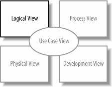 11.1.1. When Class Diagrams Won't WorkFigure 11-2 repeats a class diagram from Chapter 5, showing that BlogEntry contains objects of type Introduction and MainBody tHRough composition. Figure 11-2. Class diagram showing that BlogEntry contains Introduction and MainBody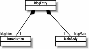 Suppose you want to update your diagrams to reflect that a blog entry's introduction has a reference to its main body because it's convenient for other objects to ask an Introduction object for the MainBody object it introduces. As a first pass, you modify the class diagram in Figure 11-2 by drawing an association between the Introduction and the MainBody classes, as shown in Figure 11-3. But there's a problem. Figure 11-3 specifies that an object of type Introduction will have a reference to an object of type MainBody, but it can be any MainBody objectnot just the one owned by the same instance of BlogEntry. That's because the association between Introduction and MainBody is defined for all instances of those types. Informally, Introduction doesn't concern itself with the composition relationship between BlogEntry and MainBody; as far as an Introduction object is concerned, all it has to do is associate with some MainBody object (but it doesn't care which one). Because Figure 11-3 doesn't specify which Introduction and MainBody objects should be associated, the object diagram in Figure 11-4 conforms to the class diagram in Figure 11-3. Figure 11-3. This first pass at showing that a blog entry's introduction introduces its main body doesn't quite work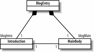 Figure 11-4. Unintended but valid object structure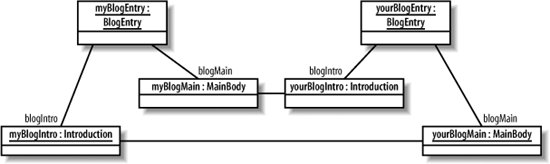 According to the class diagram in Figure 11-3, it's perfectly legal for an introduction in one blog entry to introduce the main body of another. But what you meant to say is that the introduction introduces the main body that is contained by the same class that contains the introduction, as shown in Figure 11-5. Figure 11-5. This was the intended object structure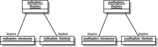 It turns out that class diagrams are not good at expressing how items contained in a class relate to each other. This is where internal structure comes in: it allows you to specify relationships in the context of the class that contains them. Right now, you may be thinking that this distinction is a bit fussy. If you're writing the code to implement these classes, you can make sure that the correct objects are linked up. You could also use a UML sequence diagram to show the objects' creation and how they get connected. But keep readingthe internal structure notation is a convenient and simple way to show relationships between contained items, especially when the contained items have complex relationships.
11.1.2. Parts of a ClassFigure 11-6 shows the internal structure of BlogEntry. Its contained items are now drawn directly inside, instead of connected through filled diamond arrowheads. Figure 11-6. The internal structure of the BlogEntry class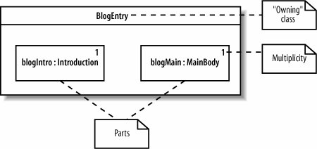 When showing the internal structure of a class, you draw its parts, or items contained by composition, inside the containing class. Parts are specified by the role they play in the containing class, written as <roleName> : <type>. In Figure 11-6, the part of type Introduction has the role blogIntro and the part of type MainBody has the role blogMain. The multiplicity, or number of instances of that part, is written in the upper righthand corner of the part. Figure 11-7 shows the internal structure diagram side by side with the class diagram from Figure 11-2, allowing you to see how the class names, roles, and multiplicities correspond. "Part"as in the parts contained by BlogEntrysounds straightforward, but it's a subtle concept. A part is a set of instances that may exist in an instance of the containing class at runtime. If that's confusing, it may help to consider the example shown in Figure 11-8, in which the part with role pic has multiplicity of zero to three in the internal structure of BlogEntry. Figure 11-7. How the internal structure of BlogEntry matches up to the class diagram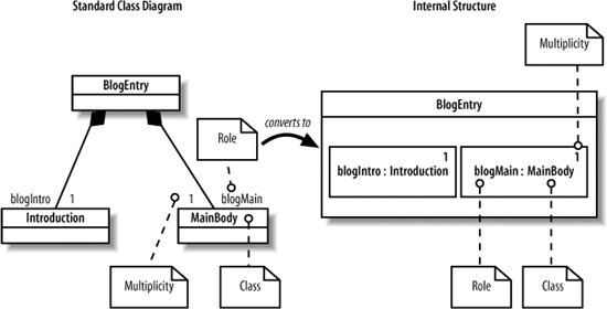 Figure 11-8. In the internal structure of BlogEntry, the part with role pic has a multiplicity of zero to three In this case, if you run across an instance of BlogEntry at runtime, it will have anywhere from zero to three instances of type Image. It may contain one Image object, it may contain three Image objects, and so on, but with parts, you don't have to worry about such details. A part is a general way to describe these contained objects by the role they play, without specifying exactly which objects are present. Because parts represent the objects that are owned by a single instance of the containing class, you can specify relationships between those specific parts and not arbitrary instances of the class types. This means you can specify that an introduction introduces the main body in the same blog entry it belongs toin other words, the introduction doesn't introduce an arbitrary main bodyand you do this with connectors. 11.1.3. ConnectorsYou show relationships between parts by drawing a connector between the parts with the multiplicities specified at each end of the connector, as shown in Figure 11-9. Figure 11-9. Using connectors to link parts in the internal structure of a class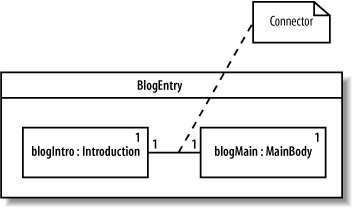
A connector is a link that enables communication between parts. A connector simply means that runtime instances of the parts can communicate. A connector can be a runtime instance of an association or a dynamic link established at runtime, such as an instance passed in as a parameter. A connector applies only to the parts it's connected toin Figure 11-9, that means only the set of instances that will exist in an instance of BlogEntry. You can now be certain that an introduction introduces the main body in the same blog entry as the introduction. 11.1.4. Alternate Multiplicity NotationsFigure 11-4 showed the multiplicity by using a number in the upper right hand corner. You can also show multiplicity in brackets after the name and type, as shown in Figure 11-10. Figure 11-10. Equivalent notations for multiplicity11.1.5. PropertiesIn addition to showing parts, which are contained by composition, you can also show properties, which are referenced through association and therefore may be shared with other classes in the system. Properties are drawn with a dashed outline, unlike parts, which are drawn with a solid outline. Figure 11-11 shows a class diagram in which Frame has an association with File, and then shows what File looks like as a property in the internal structure of Frame. Figure 11-11 models a merge tool GUI that displays the two files to compare in one panel and the merged file in another panel. Figure 11-11. Parts and properties in the internal structure of a class The notation for properties and parts is identical except for the dashed versus solid rectangle outlines: you specify roles, types, and multiplicity the same way. As with parts, properties can be connected to other properties or parts using connectors. 11.1.6. Showing Complex Relationships Between Contained ItemsShowing a class's internal structure is especially useful when its contained items relate to each other in unusual ways. Revisiting the merge tool example in Figure 11-11, suppose you want to explicitly model one panel displaying the two files being compared and the other panel displaying the merged file. You can do this by defining more detailed roles for files and panels to show how they relate to each other within a frame, as shown in Figure 11-12. Figure 11-2 demonstrates that there can be parts (or properties) of the same type playing different roles. Internal structures help make these roles and their relationships explicit. 11.1.7. Internal Structure InstancesJust as you can model instances of classes (introduced in Chapter 6), you can also show instances of classes possessing internal structure. This is essentially an object diagram for classes with internal structure. As in Chapter 6, this lets you show important examples of the objects that exist in your system at runtime. Figure 11-12. A more detailed internal structure diagram that specifies how files and panels relate to each other within a frame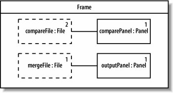 If you're showing an instance of a class with internal structure, then you also show its parts and properties as instances. Specify instances of the parts and properties by writing the name followed by a slash, then the usual role and type, e.g., {<name>} / <role> : <type>. Since these are instances, however, they are now underlined. Figure 11-13 shows an example runtime instance of the internal structure diagram shown in Figure 11-12. Figure 11-13. An instance of Frame with instances of its contained parts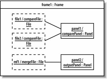 As with object diagrams, showing instances of classes with internal structure allows you to show example configurations in your runtime system. |

EAN: 2147483647
Pages: 175