Section 9.10. An Alternate Notation
9.10. An Alternate NotationReal estate on a UML diagram is almost always at a premium. In previous versions of UML, sequence diagrams were known as being the hardest diagram to manage when modeling a complex interaction. Although timing diagrams are not going to steal the sequence diagram's crown in this respect, the regular timing diagram notation shown in this chapter so far doesn't scale particularly well when you need to model a large number of different states.
The Create a new Regular Blog Account interaction's timing diagram, as shown in Figure 9-14, is actually a fairly simple example. However, you might already be beginning to grasp how large a timing diagram can getat least verticallyfor anything more than a trivial interaction that includes a small number of states. A good UML 2.0 tool will help you work with and manage large timing diagrams, but there is only so much a tool can really do. The developers of UML 2.0 realized this problem and created an alternative, simpler notation for when you have an interaction that contains a large number of states, shown in Figure 9-17. When you look closely at the alternative timing diagram notation, things are not dramatically different from the regular notation. The notation for participants and time hasn't changed at all. The big change between the regular timing diagram notation and the alternative is in how states and state changes are shown. The regular timing diagram notation shows states as a list next to the relevant participant. A state-line is then needed to show what state a participant is in at a given time. Unfortunately, if a participant has many different states, then the amount of space needed to model a participant on the timing diagram will grow quickly. The alternative notation fixes this problem by removing the vertical list of different states. It places a participant's states directly at the point in time when the participant is in that state. Therefore, the state-line is no longer needed, and all of the states for a particular participant can be placed in a single line across the diagram. To show that a participant changes state because of an event, a cross is placed between the two states and the event that caused the state change is written next to the cross. Timing constraints can then be applied in much the same way as regular notations. Bringing the subject of timing diagrams to a close, Figure 9-18 shows the alternate timing diagram notation in a practical setting: modeling the Create a new Regular Blog Account interaction. Figure 9-17. The top diagram's notation should be familiar to you, but the diagram at the bottom uses the new alternative timing diagram notation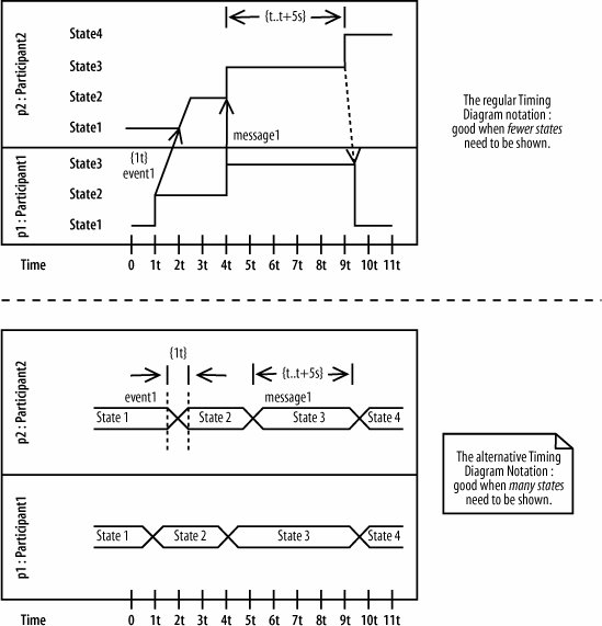
Figure 9-18. Even though there are not many states in this interaction, you can begin to see how the alternate notation is more compact and manageable in a situation where there are many states per participant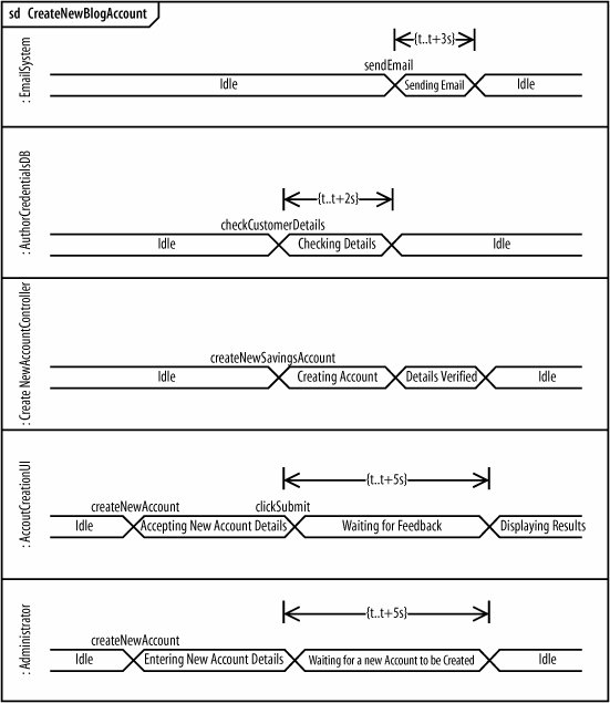 |

EAN: 2147483647
Pages: 175