12.3 Network Address Translation
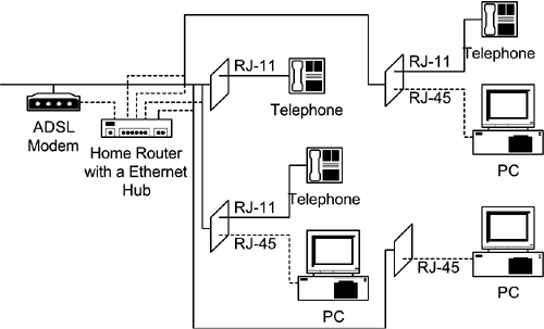
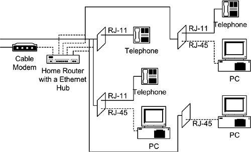
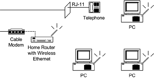
| The NBF-based peer-to-peer home network does not provide the Internet sharing capability. Windows 98 second edition and later versions include an Internet Connection Sharing (ICS) function. Sometimes, it might be more convenient to use a dedicated hardware home router to share a broadband Internet access such as an ADSL or a cable modem without paying for multiple IP addresses. Figure 12.8 shows multiple PCs sharing an ADSL via a home router with a built-in Ethernet hub. Figure 12.9 shows a similar configuration sharing a cable modem among multiple PCs. Figure 12.10 shows multiple PCs sharing a cable modem via a wireless Ethernet access point with built-in home router function. The home router obtains either a fixed or a dynamic IP address from the ISP and assigns dynamic internal IP addresses for sharing PCs. The home router can usually be configured (e.g., by entering a fixed IP address) via a Web page accessible through a connected PC. Figure 12.8. Ethernet Home Networking to Share an ADSL
Figure 12.9. Ethernet Home Networking to Share a Cable Modem
Figure 12.10. A Wireless Ethernet Sharing a Cable Modem
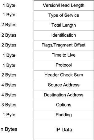
A home router can be constructed with an Ethernet NIC connecting to the ADSL or cable modem, another Ethernet NIC (or an Ethernet hub) connecting to a PC (or PCs), and a Network Address Translation (NAT) process. A home router with a built-in Ethernet hub also enables a peer-to-peer home network in conjunction with the NBF protocol. A wireless Ethernet home router also consists of an Ethernet NIC connecting to the ADSL or cable modem and a NAT process in addition to its IEEE 802.11 access point capabilities. NAT normally indicates the dynamic mapping of a group of public IP addresses to private IP addresses on demand to reduce the number of IP addresses required for a particular organization. For a household to share one IP address among multiple PCs also involves the dealing of port numbers [6]. Figure 12.11 shows the format of an IP packet including source and destination addresses of 4 bytes each. The Header Checksum is the 16-bit one's complement of the one's complement sum of all 16 bit words in the header. For purposes of computing the Header Checksum, the value of the Header Checksum field is zero. The Options can be 0, 1, or 3 bytes. Corresponding padding will be 0, 3, or 1 bytes of zeros to make the header a multiple of 4 bytes. Figure 12.11. IP Packet Format
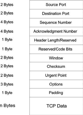
The total number of IP addresses defined by 4 bytes is large enough (about 4.3 billion), but because of routing issues, they can only be used in blocks. There are three common classes (A, B, and C) for IP addresses with 7, 14, and 21 bits allocated for network IDs and 24, 16, and 8 bits set aside for host IDs after 1, 2, and 3 initial bits are excluded for class identifications, respectively. Therefore each class is capable of providing 126, 16,256, and 2,064,512 networks with 16,777,214, 65,534, and 254 hosts for each network, respectively. Addresses with all 0s and all 1s have been reserved for self-identification and broadcast. A network ID is usually identified by an organization, and a host ID, by a computer within that organization. The network ID is usually used for routing purposes. To allow more computers access to the Internet, an organization can use a NAT to allocate dynamically available IP addresses to computers that are actively using the Internet. Blocks of IP addresses, 10.0.0.0 through 10.255.255.255 for Class A, 172.16.0.0 through 172.31.255.255 16 for Class B, and 192.168.0.0. through 192.168.255.255 255 for Class C, have been reserved as internal IP addresses. A NAT not only keeps a map relating internal IP addresses of active computers to these assigned public IP addresses but also replaces an internal source IP address with a mapped public IP address when sending a packet to the Internet and replaces the corresponding public destination IP address with the mapped Internal IP address when receiving a packet from the Internet before delivering it through the internal network. A NAT also needs to recalculate and replace the Header Checksum after replacing an IP address. For the home network environment where only one IP address is available, the use of port numbers is necessary for the NAT process. IP data within an IP packet are usually represented in either a TCP or a UDP packet format. Port numbers are within a TCP or UDP packet header. Figure 12.12 shows the format of a TCP packet. A TCP packet contains Source and Destination Port numbers of 2 bytes each. The Checksum field is the 16-bit one's complement of the one's complement sum of all 16-bit words in the header and TCP data. While computing the checksum, the checksum field itself is replaced with zeros. The checksum also covers a 96-bit pseudo header conceptually prefixed to the TCP header. This pseudo header contains the source address, destination address, protocol number, and TCP packet length and protects the TCP against misrouted segments. The TCP header padding, composed of zeros, is used to ensure that the TCP header ends and data begins on a multiple of 4 bytes. Figure 12.12. TCP Packet Format
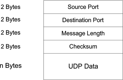
Figure 12.13 shows the format of a UDP packet. A UDP packet also contains Source and Destination Port numbers of 2 bytes each. The checksum is a 16-bit one's complement of the one's complement sum of a pseudo header of information from the IP header, the UDP header, and the data, padded with zero bytes at the end (if necessary) to make a multiple of 2 bytes. The pseudo header, conceptually prefixed to the UDP header, contains the source address, the destination address, the protocol number, and the UDP packet length. This information gives protection against misrouted datagrams. While computing the checksum, the Checksum field itself is also replaced with zeros. Figure 12.13. UDP Packet Format
Port numbers are normally used for identifying particular applications. Port numbers smaller than 256 are assigned to public applications. For example, port numbers 25 and 80 are assigned for SMTP (Simple Mail Transfer Protocol)-based e-mail and HTTP (Hypertext Transfer Protocol)-based Web services, respectively. Port numbers of 256 to 1023 are assigned to identify certain commercial network application products. Port numbers larger than 1023 can be dynamically assigned by user applications including the NAT. NAT, using dynamically assigned port numbers, is referred to as Masquerading (by Linux) or NAPT (Network Address Port Translation). In Linux convention, port numbers 61000 to 65096 are utilized for NAPT. An NAPT process with a single public IP address keeps a map relating internal IP addresses (with specific port numbers of active computers) to dynamically assigned port numbers. The NAPT replaces an internal source IP address and associated port number with its own public IP address and a mapped port number when sending a packet to the Internet. The NAPT replaces its own IP destination address and the associated port number with a mapped internal IP address and associated port number when receiving a packet from the Internet before delivering it through the internal network. After replacing an IP address, an NAPT also needs to recalculate and replace the header checksum as well as the checksum of a TCP or UDP packet after replacing a port number. Figure 12.14 shows a home router NAPT example. The top path shows an IP packet originated from a PC with an internal IP address of 11.4.6.12 and port number of 1257 to reach a Web server with a public IP address of 193.46.94.115 and a port number of 80. The home router has an internal IP address of 11.4.6.1 and a public IP address of 195.112.12.161. All internal IP addresses are assigned by the home router via DHCP. The bottom path shows a returning packet from the Internet. Figure 12.14. A Home Router NAPT Example
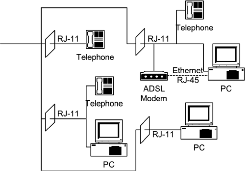
A home router with an NAPT acts as a firewall protecting all internally shared files because Internet connections can be initiated only within the home network. A hardware home router is usually not much more expansive than an Ethernet hub and can be left on all the time without consuming much power. A PC with a Windows 98 second edition or later operating system and two NICs can also be configured as a home router. Figure 12.15 shows a PC with an Ethernet NIC connected to an ADSL and a HomePNA NIC connected to other PCs via existing telephone wiring for Internet sharing. The Internet Connection Sharing (ICS) needs to be installed by selecting the Add/Remove Programs icon within the Control Panel to make a PC act as a home router. The ICS module can be further identified under the Internet Tools on the Add/Remove Programs Properties screen. Once selected, an Internet Connection Sharing Wizard will guide you through the rest of the installation process for the home router PC. Because ICS is also an NAPT, other PCs should set up their TCP/IP configurations to obtain internal IP addresses automatically from the home router PC. Figure 12.15. A HomePNA Home Network Sharing an ADSL
|
EAN: 2147483647
Pages: 97
