11.1 Media Access Control Basics
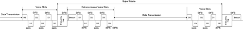
| The HomeRF MAC is designed to handle both asynchronous data and TDMA (Time Division Multiple Access) voice packet transmissions. On the other hand, the point coordination function part of IEEE 802.11 MAC is designed to handle timing-sensitive applications through a polling system. HomeRF can be viewed as a specialized version of IEEE 802.11 wireless Ethernet whose MAC is a combination CSMA/CA of IEEE 802.11 and TDMA of DECT and that uses the FHSS modulation method of IEEE 802.11. To guarantee the periodic delivery of voice packets, a superframe is defined for HomeRF. A frequency hop starts every superframe. Original voice packet transmissions are allocated near the end of the superframe, and retransmission of voice packets is allowed right after the frequency hop at the beginning of the superframe to benefit from the frequency and time diversity. Asynchronous data transmission occurs after a DIFS. The reception of every asynchronous data packet is acknowledged by a short packet within a SIFS. On the other hand, all voice packets are separated by a SIFS. Therefore, asynchronous data transmission can start a DIFS after the frequency hop if there is no retransmission voice packets. Different HomeRF MAC frames are defined for management tasks, asynchronous data transmissions, and TDMA connections. For security purposes, HomeRF uses a different encryption algorithm than the WEP of IEEE 802.11. 11.1.1 Simultaneous TDMA and CSMA/CAHomeRF provides both data and voice transmission capabilities based on 802.11 FHSS GFSK signaling methods. To maintain constant connections, voice packets need to be delivered periodically with minimal jitter; therefore, a periodic superframe is defined to accommodate the needs of voice connections. The period of the superframe depends on the voice packet size and the throughput of each voice connection. For example, if the voice packet size is 640 bits and the throughput of each voice channel is 32 kbps, the period of the superframe is 640/32 x 103 = 20 ms. Two voice packet time slots are required for each full-duplex voice connection. Because each voice packet occupies a relatively small portion of time, multiple pairs of voice packet slots, corresponding to multiple voice connections, can be located in each superframe. To ensure reliability, retransmission voice slots are also allocated after a frequency hop to avoid an unfavorable transmission environment. After retransmission voice slots, the remaining time of the superframe is available for asynchronous data transmission. Figure 11.1 shows the general structure of a HomeRF superframe. Figure 11.1. Superframe Structure
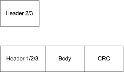
Up to four pairs of voice slots and four pairs of retransmission slots can be allocated in each superframe. All voice slots are separated by SIFS while pending data packets need to wait for a DIFS. The duration of a super frame is actually marked from the start of a frequency hop to the next frequency hop. Under this definition, retransmission voice slots appear right after the Beacon frame. Asynchronous data transmission starts whenever a DIFS can be detected. Voice slots start by counting backwards from the end of the superframe or the next frequency hop time. The information on the number of voice slots is broadcast by the Beacon frame. Data transmissions are constrained not to extend to these voice slots. A SIFS lasts about 142 µs and a DIFS lasts about 309 µs. With 1-Mbps GFSK, a voice packet lasts about 1 ms. On the other hand, the Beacon frame takes about 1.3 ms. We also give the frequency hop process about 300 µs. Therefore, a 20-ms superframe can provide a duration of about 18.258 ms for packet transmission after the deduction of the frequency hop and Beacon frame overhead. The duration is just about enough for allocating four pairs of voice slots and four pairs of retransmission slots. In other words, if four voice connections are allocated in an unfavorable transmission environment, data transmission throughput will be reduced to below 0.5 Mbps depending on how often retransmission occurs. On the other hand, a maximum of 17,949 asynchronous symbols can be transmitted during a superframe with no voice or retransmission slots considering the DIFS. This leads to a maximum payload of about 17,621 bits, or about 2202 bytes, with the 1-Mbps GFSK modulation considering preamble, header, and CRC overhead. This is a little less than the maximum payload size of 2312 bytes defined by IEEE 802.11 standards. In practice, one or two voice connections can be established simultaneously with data transmission throughputs of about 0.8 Mbps, assuming retransmission happens not very often with the 1-Mbps GFSK modulation. Asynchronous data packets are transmitted using the CSMA/CA algorithm. The reception of every data packet is acknowledged by a short ACK packet within the SIFS. A HomeRF SIFS is defined as the time for transmission delay, CRC calculation, and turning around a transceiver from a receive mode to a transmit mode. A HomeRF DIFS is defined as the SIFS plus a slot duration. A slot duration is defined as the time for a transceiver to perform a CCA operation. To avoid potential collision, transceivers wait for additional random slot durations after the DIFS before sending their pending packets. Management frames are also transmitted during the asynchronous data transmission time period. Each voice channel is sampled at 8 kHz with a resolution of 14 bits producing a PCM (Pulse Code Modulation) bit stream. Each voice bit stream is companded and encoded into a sequence of 4-bit ADPCM (Adaptive Differential Pulse Code Modulation) codewords. Each HomeRF voice packet corresponding to a voice channel throughput of 32 kbps contains 160 ADPCM codewords, or 640 bits and some control information. A single voice packet is transmitted in each voice time slot. Two voice time slots, one from a CP to an I-node called downstream and the other in the reverse direction called upstream, are paired. Voice slots are scheduled during the voice connection set-up process. The reception of each downstream voice packet is acknowledged by an indication bit in the header of the corresponding upstream voice packet. If the voice packet is received incorrectly, the CP schedules a pair of retransmission slots and advertises this coming event in the Beacon packet. The retransmission for each mission packet can only be scheduled once. A single service slot can be added right after the retransmission slots or the Beacon packet if no retransmission is scheduled. The service slot is used by an I-node to send management information and is created by the sending of a management frame within the SIFS. A contention resolution procedure is defined in case multiple I-nodes use the service slot at the same time. 11.1.2 MAC FramesFigure 11.2 shows these general HomeRF MAC frame formats as defined by the standards. A HomeRF MAC frame can have a type 2 or 3 header only or a type 1, 2, or 3 header followed by a MAC frame body and its CRC. Figure 11.2. MAC Frame Formats
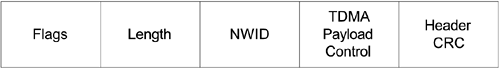
The HomeRF type 1 header is associated with a TDMA MAC frame body and consists of 9 bytes. The type 2 header is associated with a CSMA/CA MAC frame. The type 3 header is associated with a CSMA/CA MAC frame carrying synchronization information. The type 1 header has a Flags field of 10 bits, a Length field of 14 bits, an NWID (Network ID) field of 24 bits, a TDMA Payload Control field of 8 bits, and a header CRC field of 16 bits as shown in Figure 11.3. Figure 11.3. HomeRF Type 1 Header
The HomeRF type 2 header is associated with CSMA/CA MAC frames and additionally has a Destination Address and Source Address fields of 48 bits each as shown in Figure 11.4. Figure 11.4. HomeRF Type 2 Header
The HomeRF type 3 header includes a synchronization information field of 32 bits each as shown in Figure 11.5. Figure 11.5. HomeRF Type 3 Header
The flags field consists of the following subfields: version of 2 bits, learn NWID of 1 bit, MAC frame type of 5 bits, and reserved of 2 bits. There are 10 distinguishable MAC frame types associated with these three types of headers. The Length field contains the number of symbols to the end of a packet, starting from the beginning of the NWID field. The NWID field identifies the network with which a node is associated. The TDMA Payload Control field consists of the following subfields: connection ID of 2 bits, request encryption of 1 bit, encrypted payload of 1 bit, reserved of 1 bit, and TDMA Ack of 1 bit. The Payload Control field for CSMA/CA MAC frames consists of the following subfields: modulation level of 2 bits, encryption level of 2 bits, compressed of 1 bit, First Frag of 1 bit, Last Frag of 1 bit, and Frag SN of 1 bit. First Frag and Last Frag are used to indicate the first and last fragments of a fragmented payload. Frag SN is alternately set to 1 or 0 for fragments between the first and the last ones. The synchronization information field consists of a hop pattern subfield of 8 bits, a hop index subfield of 8 bits, and DW count subfield of 16 bits. The DW count value is the number of symbol periods remaining in the dwell period after the transmission of the MAC frame header. The MAC frame header is protected by a 16-bit CRC generated according to Equation 11.1
The MAC frame header CRC is the 1's complement of the exclusive OR of the remainder of xk (x15 + x14 +... + x + 1 divided by G(x) and the remainder of the message polynomial multiplied by x16 and then divided by G(x), where k is the number of MAC frame header bits. As a typical implementation, at the transmitter, the initial remainder of the division is preset to all 1's and is then modified by division of the message polynomial by the generator polynomial G(x). The 1's complement of this remainder is transmitted, with the highest order bit first, as the CRC field. At the receiver, the initial remainder is preset to all 1's, and the serial incoming bits of the MAC frame header and CRC, when divided by G(x), results in a unique nonzero polynomial, G(x) = x12 + x11 + x10 + x8 + x3 + x2 + x + 1, in the absence of any transmission error. The MAC frame body is protected by a 32-bit CRC generated according to Equation 11.2
The MAC frame body is the 1's complement of the exclusive OR of the remainder of xk (x31 + x30 + x29 + ... + x2 + x + 1 divided by G(X) and the remainder of the MAC frame body polynomial multiplied by x32 and then divided by G(x), where k is the number of MAC frame body bits. As a typical implementation, at the transmitter, the remainder of the division is initially preset to all 1's and is then modified by dividing of the message polynomial by the generator polynomial G(x). The 1's complement of this remainder is transmitted, with the highest order bit first, as the FCS field. At the receiver, the remainder is initially preset to all 1's and the serial incoming bits of the message and FCS, when divided by G(x), results in a unique nonzero polynomial Equation 11.3
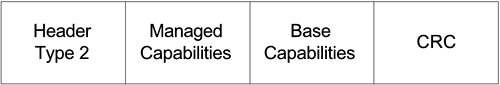
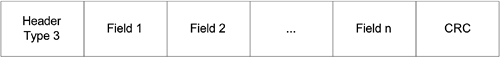
in the absence of any transmission error. There are seven HomeRF MAC frame types: Information Request and Station Information (IR and SI), Data, TDMA, Connection Point Service (CPS), Ad-hoc Beacon, CP Beacon, and Connection Point Assertion. The IR and SI frame format is as defined in Figure 11.6. An IR and SI frame has a Type 2 header of 21 bytes, a Managed Capabilities field of 1 byte, and a Base Capabilities field of 1 byte and is followed by a 4-byte CRC. An IR and SI frame carries the transmitting node modulation, compression, transmit power, power savings, and TDMA capabilities. Figure 11.6. IR and SI Frame Format
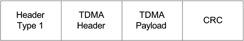
The Data frame can have a type 2 or type 3 MAC frame header, depending on whether synchronization information is included, followed by a MAC frame body of the CSMA/CA type defined by IEEE 802.11 standards. The TDMA MAC frame format is defined by Figure 11.7. A TDMA frame has a type 1 Header of 9 bytes, a TDMA Header of 1 byte, and a TDMA Payload of 85 bytes and is followed by a 4-byte CRC. TDMA frames are used to establish full-duplex isochronous communication links for voice applications. Figure 11.7. TDMA MAC Frame Format
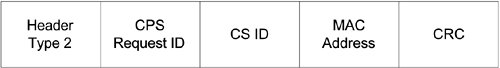
The CPS frame is as defined in Figure 11.8. A CPS frame has a Type 2 Header of 21 bytes, a CPS request ID of 1 byte, a CSID (service ID of a power management request) of 1 byte, and a MAC Address of 6 bytes and is followed by a 4-byte CRC. A CPS frame is used by a transceiver for service management. Figure 11.8. CPS Frame Format
The Ad-hoc Beacon frame consists of only a Type 3 Header and is used by an ad-hoc network to maintain synchronization. The CP Beacon frame format is as defined in Figure 11.9. A CP Beacon frame has a Type 3 Header and a number of variable size fields. A CP Beacon frame can consist of only a header and a CRC but no other fields. Other valid fields include Main TDMA Slot, Retry TDMA Slot, Power Management, Broadcast Service, and Connection Management. The maximum size of a CP Beacon payload of all fields is that of the TDMA payload. Figure 11.9. CP Beacon Frame Format
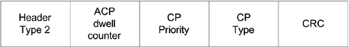
The Connection Point Assertion frame has the frame format as defined in Figure 11.10. A CP Assertion frame has a Type 2 Header of 21 bytes, an ACP dwell counter of 4 bytes, a CP Priority field of 4 bits, and a CP Type field of 4 bits and is followed by a 4-byte CRC. A CP Assertion frame is broadcast by an active CP to ensure that there is only one active CP on the network. Figure 11.10. CP Assertion Frame Format
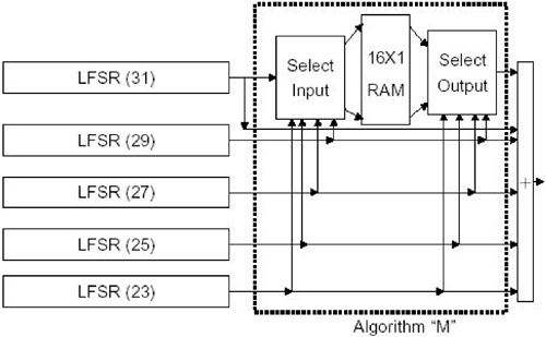
11.1.3 EncryptionA linear feedback shift register (LFSR)-based encryption algorithm has been proposed for HomeRF application. The encryption can be applied either to asynchronous data or to isochronous voice packets. Inputs to the encryption process are an encryption key, an initialization vector of 32 bits, and a data or voice bit stream. The output from this encryption process is a bit stream of the same length as that of the input data or voice. Figure 11.11 shows a block diagram of the encryption algorithm. There are five LFSRs of lengths 23, 25, 27, 29, and 31. Four of these combine to form an address. The other forms the data into the "Algorithm M." The encryption key and IV are initially distributed into these bits of LFSR registers. The output of Algorithm M is combined with the outputs of all the shift registers to produce output bits. These output bits are exclusive-ORed with the bits of the input data or voice to produce the encrypted bit stream. Figure 11.11. A Block Diagram of the Encryption Algorithm
|
EAN: 2147483647
Pages: 97