10.5 Orthogonal Frequency Division Multiplexing
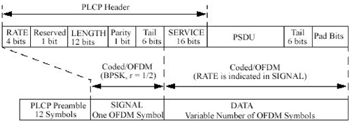
| A 64-point complex number IFFT/FFT operation forms the modulation mechanism for this 802.11a wireless Ethernet. Among 64 subcarriers, 48 of them are used for BPSK, QPSK, 16) Quadrature Amplitude Modulation (QAM), or 64QAM, 4 of them are used for pilot tone. Complex time domain signals are modulated onto in-phase and quadrature channels of an RF carrier separately. A rate 1/2 convolution code is used for error protection. Rate 2/3 and 3/4 codes are derived through puncturing. An interleaving process is used to randomize subcarrier and bit location distribution among each OFDM symbol. 10.5.1 Summary of 802.11a StandardsThe packet format for the OFDM implementation of wireless Ethernet at 5 GHz is shown in Figure 10.53. An OFDM packet consists of a preamble, a header, and a MAC frame. The OFDM preamble has a Sync field of 10 short symbols and 2 long symbols. The OFDM header has 1 Signal symbol including a Rate field of 4 bits, followed by a reserved bit, a Length field of 12 bits, followed by a parity bit and 6 tail bits. The MAC frame is further encapsulated with a Service field of 16 bits in the beginning and 6 tail bits as well as some necessary PAD bits at the end. Figure 10.53. OFDM Packet Format (From IEEE Std. 802.11. Copyright © 1999 IEEE. All rights reserved.)
The OFDM preamble Sync field is to be used by the receiver to detect a signal and to achieve initial frequency and timing synchronization to receive the rest of the packet. The preamble lasts 16 µs as shown in Figure 10.54. Short preamble symbols are indicated by t1 through t10, and long preamble symbols are labeled as T1 and T2. Figure 10.54. Preamble Structure (From IEEE Std. 802.11. Copyright © 1999 IEEE. All rights reserved.)
A normal OFDM symbol is created through the inverse fast Fourier transform of data bits in a transmitter. Data bits are recovered in a receiver using the fast Fourier transform. The IFFT/FFT size for 802.11a is 64. Each IFFT/FFT block has 64 complex time domain points and 64 complex subcarriers in frequency domain. Complex time domain signals are represented by in-phase and quadrature parts of an OFDM wireless Ethernet carrier frequency. The interval between adjacent time points is 50 ns corresponding to a base sampling rate of 20 MHz. The duration of an IFFT/FFT block T is 64 x 50 = 3.3 µs. The frequency between adjacent subcarriers is therefore 20 MHz/64 = 312.5 kHz. Among these subcarriers, 48 are used for carrying data bits, 4 are reserved for pilot tones with carrier/timing information, carrier 1 is not used for avoiding DC bias, and carriers 28 38 are not used for minimizing interference between coallocated 802.11a wireless Ethernet systems using adjacent channel frequencies. To avoid channel intersymbol interference, a cyclic prefix of 16 points is appended in front of each time domain OFDM symbol. A normal OFDM symbol duration is therefore 80 x 50 ns = 4 µs. The OFDM symbol rate is 250 kHz. A short preamble symbol is created by IFFT for the sequence The Signal field of 24 bits contains Rate and Length subfields. The first 4 bits encode the Rate information. The fifth bit is reserved for future use. The next 12 Length bits indicate the number of bytes for the MAC frame before encapsulation. The following bit is a positive parity (even parity) bit for the previous 17 bits. The last 6 bits constitute the Signal Tail field and are all zeros. The size of the signal field is doubled to 48 bits after the rate 1/2 convolution encoding, and these 48 bits are mapped to 48 data-carrying subcarriers to create the single Signal OFDM symbol with BPSK modulation. The Service field before the MAC frame consists of 16 bits. The first 7 bits are zeros and are used to synchronize the descrambler in the receiver; the remaining 9 bits are reserved for future use. These 6 tail bits, which are required to reset the convolutional encoder, after the MAC frame are also all zeros. A number of PAD bits are added to make the encapsulated MAC frame fill a multiple number of whole OFDM symbols of 48, 96, 192, or 288 bits. The encapsulated MAC frame is scrambled with a length-127 frame-synchronous pseudo-random sequence. This pseudo-random sequence is created using the generator polynomial as described by Equation 10.33
Figure 10.55 shows a possible implementation of this frame-synchronous scrambler. The encapsulated MAC frame is also coded with a binary convolution encoder of coding rate R = 1/2, 2/3, or 3/4, corresponding to the desired data rate. The rate 1/2 binary convolution code is defined by Equation 10.34
Figure 10.55. Scrambler Implementation (From IEEE Std. 802.11. Copyright © 1999 IEEE. All rights reserved.)
or in octal form shown by Equation 10.35
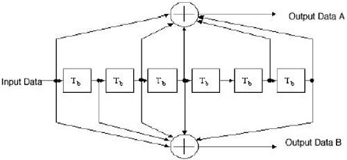
The convolution-encoding process can be implemented with six delay elements and exclusive OR operations as shown in Figure 10.56. For every data bit input, two output bits A and B are generated. Bit A is taken out ahead of bit B. Figure 10.56. Convolution Encode Implementation (From IEEE Std. 802.11. Copyright © 1999 IEEE. All rights reserved.)
Higher convolution encoding rates are derived from this encoder by puncturing. Puncturing is a procedure for omitting some of the encoded bits in the transmitter (thus reducing the number of transmitted bits and increasing the coding rate) and inserting dummy zeros into the convolutional decoder on the receive side in place of the omitted bits. For rate 2/3 encoding, starting with the first pair of encoded bits, the puncturing procedure takes away a B output bit from the second pair and repeats this process for every group of two pairs. For rate 3/4 encoding, starting with the first pair of encoded bits, the puncturing procedure takes away a B output bit from the second pair and an A output bit from the third pair and repeats this process for every group of three pairs. Interleaving across multiple subcarriers within a symbol is performed on these convolution encoded bits before modulation to randomize subcarrier and bit position distribution. The interleaving block size corresponds to the number of bits in a single OFDM symbol, NCBPS. The interleaver is defined by a two-step permutation. The first permutation ensures that adjacent coded bits are mapped onto nonadjacent subcarriers. The second ensures that adjacent coded bits are mapped alternately onto less and more significant bits of the constellation. We denote k as the index of the encoded bit before the first permutation, i as the index after the first and before the second permutation, and j as the index after the second permutation. The first permutation is defined by Equation 10.36
The function floor( ) denotes the largest integer not exceeding the parameter (i.e., floor[5.6] = 5). The second permutation is defined by Equation 10.37
The value of s is determined by the number of coded bits per subcarrier NBPSC according to Equation 10.38
The second permutation effectively is not required for NCBPS = 48 and s = 1. For NCBPS = 48, s = 1, and k = 7, we have i = 21 and j = 21; and for NCBPS = 192, s = 4, and k = 7, we have i = 84 and j = 85. The deinterleaver, which performs the inverse relation, is also defined by two permutations. We denote j as the index of the original received bit before the first permutation, i as the index after the first and before the second permutation, and k as the index after the second permutation. The first permutation is defined by Equation 10.39
where s is defined in Equation 10.38. The second permutation is defined by Equation 10.40
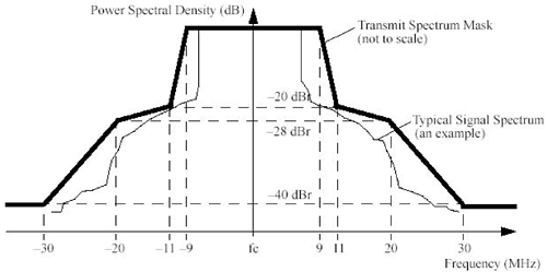
For NCBPS = 48, s = 1, and j = 21, we have i = 21 and k = 7; for NCBPS = 192, s = 4, and j = 85, we have i = 84 and j = 7. We can have BPSK, QPSK, 16QAM, and 64QAM for subcarrier modulations depending on the RF channel SNR. Each subcarrier for a particular encapsulated MAC frame uses the same modulation method. Each OFDM symbol can therefore carry 48, 96, 192, or 288 bits corresponding to BPSK of 1 bit, QPSK of 2 bits, 16QAM of 4 bits, and 64QAM of 6 bits per subcarrier. Combined with convolution encoding ratio of 1/2, 2/3, or 3/4 and a symbol rate of 250 kHz, available OFDM wireless Ethernet transmission throughputs are 6, 9, 12, 18, 24, 36, 48, and 54 Mbps. They use 1/2 and BPSK, 3/4 and BPSK, 1/2 and QPSK, 3/4 and QPSK, 1/2 and 16QAM, 3/4 16QAM, 2/3 and 64QAM, and 3/4 and 64QAM encoding ratios and modulation methods, respectively. The transmit power of an OFDM wireless Ethernet is limited to 40, 200, and 800 mW for 5.15 5.25, 5.25 5.35, and 5.725 5.825 GHz frequency bands, respectively. There are four OFDM wireless Ethernet channels defined for each of the above three frequency bands. These carrier frequencies are 5.18, 5.20, 5.22, 5.24, 5.26, 5.28, 5.30, 5.32, 5.745, 5.765, 5.785, and 5.805 GHz. Adjacent channels are 20 MHz apart. The PSD of each OFDM wireless Ethernet channel is defined by the mask as shown in Figure 10.57. PSD limits are 56.5, 49.5, and 43.5 dBm/Hz for a signal bandwidth of 18 MHz for these three frequency bands, respectively. Figure 10.57. OFDM Channel PSD MASK (From IEEE Std. 802.11. Copyright © 1999 IEEE. All rights reserved.)
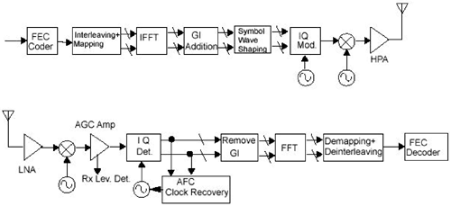
10.5.2 Transceiver Architecture and Performance EstimationFigure 10.58 shows functional block diagrams of an OFDM wireless Ethernet transmitter and a corresponding receiver. In the transmitter, data information bits pass through a convolution encoder and an interleaver and are then mapped into these 48 subcarriers for IFFT. A Guide Interval (GI), also known as the cyclic prefix, is created for each symbol by duplicating the last 16 points of the IFFT outputs in front of the original 64-point outputs. Real and imaginary parts of the symbol in time domain are filtered separately before being modulated onto the in-phase and the quadrature parts of an Intermediate Frequency carrier, respectively. The IF carrier is then modulated into the desired OFDM RF channel. In the receiver, the received RF signal is demodulated in an IF carrier. The IF carrier is then demodulated into separate in-phase and quadrature channels after IF amplification and AGC. The GI is removed before these in-phase and quadrature signals, representing the real and imaginary parts of the input, are sent through the FFT operation. Outputs from the FFT are converted into a serial bit stream after deinterleaving and demapping. Data bits are recovered after convolution decoding, which can be implemented with the Viterbi algorithm. Figure 10.58. An OFDM Transceiver Structure (From IEEE Std. 802.11. Copyright © 1999 IEEE. All rights reserved.)
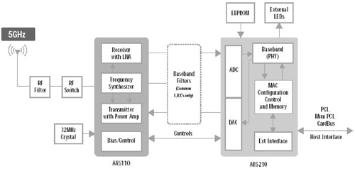
Figure 10.59 shows an example of a OFDM transceiver chip set from Atheros. This chip set consists of a baseband/MAC part (AR5210) and an RF part (AR5110). ADCs and DACs are contained in the baseband/MAC part. The host interface function is also included in the baseband/MAC part. The RF part contains RF/IF receive amplification and demodulation functions including LNA, RF/IF transmit modulation and amplification functions including PA, a frequency synthesizer, and some bias/control functions. This chip set needs external crystals, an RF filter, a transmit/receive switch, baseband filters, and an external Erasable Programmable Read-Only Memory (EPROM) memory chip to form an OFDM transceiver. Figure 10.59. An OFDM Transceiver Chip Set Example
The transmit power of an OFDM transceiver is defined to be limited at 16, 23, and 29 dBm for these three frequency bands, respectively. An OFDM transceiver needs to operate under the received signal level of 30 dBm when transceivers are close by. The receive sensitivities are required to be 82, 81, 79, 77, 74, 70, 66, and 65 dBm for 6, 9, 12, 18, 24, 36, 48 and 54 Mbps transmission throughputs, respectively. The allowed signal attenuation is between 81 and 111 dB depending on the transmit power level and the desired receiver sensitivity. The maximum operable distance between OFDM transceivers is similar to or a little shorter than those between HRDSSS transceivers. The receiver front-end noise level is a little higher than that of DSSS because it has a wider bandwidth and is equal to 87.44 dBm. At a signal-to-noise level of about 13.59 dB, the channel capacity for the DSSS environment is B = 20 MHz: Equation 10.41
Using the channel capacity calculation expression The transmission performance of an OFDM wireless Ethernet transceiver can be further studied by computer simulation. Figure 10.60 shows a simplified Simulink model that consists of a random data sequence generator, a transmitter, a multipath channel model, and a receiver. Figure 10.60. A Simulink OFDM Simulation Model
Figure 10.61 shows the internal structure of the Simulink transmitter model. A binary data sequence is first passed through the rate 1/2 convolution encoder. Convolution-encoded bits are then formulated into 52 complex numbers corresponding to these subcarriers for IFFT operation. Complex number outputs from IFFT are converted to serial with prefixes added for in-phase and quadrature channels separately. The carrier modulation process is omitted to use the complex multipath channel model. Figure 10.61. The Simulink OFDM Transmitter Model
Figure 10.62 shows the implementation of the constellation encoder with a serial-to-parallel convertor and 52 individual 4QAM, or QPSK, encoding cells. Zeros are inserted at subcarriers 1 and 28 38 corresponding to the subsequent IFFT operation. Figure 10.62. A Possible Encoder Implementation
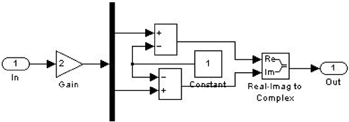
Figure 10.63 shows the possible implementation of a 4QAM encoding cell. Two bits are separately used to drive the real and imaginary parts of a subcarrier. Figure 10.63. A 4QAM Encoding Cell
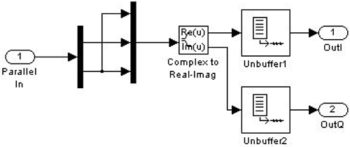
Figure 10.64 shows the possible implementation of the prefix addition and parallel-to-serial conversion function block. The last 16 points of the IFFT output are repeated in front of the 64-point original output to create an 80-point complex time domain symbol. Real and imaginary parts are separated for the multipath channel model for this simulation and for separate in-phase and quadrature channel modulations in a real implementation. Figure 10.64. Transmit Parallel-to-Serial and Prefix Addition Function
Figure 10.65 shows the internal structure of the Simulink receiver model. Prefixes are removed before received signals are converted to frames of 64 complex numbers for FFT operation. Outputs from the FFT are decoded into a bit stream by the constellation decoder. Data bits are recovered using the Viterbi decoder. Figure 10.65. The Simulink OFDM Receiver Model
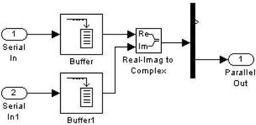
Figure 10.66 shows a possible implementation of the received signal serial-to-parallel conversion and prefix removal functional block. Figure 10.66. Receiver Serial-to-Parallel and Prefix Removal Function
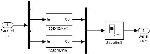
Figure 10.67 shows that the constellation decoder is made up of 52 individual 4QAM decoding cells followed by a parallel-to-serial convertor. Figure 10.67. A Possible Decoder Implementation
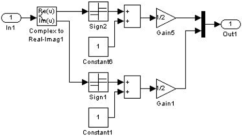
Figure 10.68 shows the possible implementation of a 4QAM decoding cell. Complex inputs are separated into a real part and an imaginary part for level-to-bit conversion. Figure 10.68. A 4QAM Decoding Cell
|
EAN: 2147483647
Pages: 97
