Deploying a VPN Remote Access Server Solution
Deploying a remote access server solution involves configuring the server as a VPN remote access server; configuring routing on the VPN server and the VPN clients; and implementing security — installing any certificates required for the authentication of remote clients, configuring encryption in requirements the remote access policy for VPN connections, and optionally configuring remote access account lockout. Figure 8.7 shows the process for deploying a VPN remote access server solution.
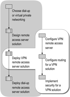
Figure 8.7: Deploying a VPN Remote Access Server Solution
| Important | The procedures for deploying a VPN remote access server solution assume that you have deployed Active Directory on the server, have a PKI in place, and have deployed an IAS server. For information about designing and deploying a PKI, see "Designing a Public Key Infrastructure" in Designing and Deploying Directory and Security Services of this kit. For information about designing and deploying IAS, see "Deploying IAS" in this book. For more information about Active Directory, see "Designing the Active Directory Logical Structure" in Designing and Deploying Directory and Security Services of this kit. |
Configuring a VPN Remote Access Server
The configuration of a VPN remote access server involves the following tasks:
-
Configure the server as a VPN remote access server.
-
Configure TCP/IP on the server.
-
Configure name resolution on the server.
-
Configure packet filters for the server.
-
Optionally, configure Network Access Quarantine Control.
Configuring the Server as a VPN Remote Access Server
To configure the server as a VPN remote access server, use the Configure Your Server Wizard and select Remote access/VPN server as the server role, or use the Rounting and Remote Access snap-in. For instructions on using the wizard, see "Remote access/VPN server role: Configuring a remote access/VPN server" in Help and Support Center for Windows Server 2003.
Configuring TCP/IP on the VPN Server
After configuring the server as a remote access server, configure the TCP/IP settings for the Internet or perimeter network interface and for the intranet interface.
| Note | Because of routing issues related to configuring TCP/IP automatically, it is recommended that you not configure a VPN server as a DHCP client. Instead, manually configure TCP/IP on the intranet interfaces of a VPN server. For a full discussion of the routing options for a VPN server, see "Configuring Routing on a VPN Server" later in this chapter. |
Manually configure the Internet or perimeter network interface of the VPN server with a default gateway. Configure the TCP/IP settings with a public IP address, a subnet mask, and the default gateway of either the firewall (if the VPN server is connected to a perimeter network) or an ISP router (if the VPN server is connected directly to the Internet).
-
To configure TCP/IP for the Internet or perimeter network interface
-
In Control Panel, double-click Network Connections, and then double-click the network adapter for the Internet or perimeter network interface.
-
In the network adapter status dialog box (for example, Local Area Connection Status), click Properties.
-
Select Internet Protocol (TCP/IP), and then click Properties.
-
On the General tab, configure the IP address, subnet mask, and default gateway.
The IP address must be a public IP address assigned by an ISP. As an option, you can configure the VPN server with a private IP address but assign it a published static IP address by which it is known on the Internet. When packets are sent to and from the VPN server, a NAT that is positioned between the Internet and the VPN server translates the published IP address to the private IP address.
When you configure a VPN connection, give your VPN servers names that can be resolved to IP addresses using DNS.
-
Click Advanced to display the Advanced TCP/IP Settings dialog box.
-
To prevent the VPN server from dynamically registering the public IP address of its Internet interface with an intranet DNS server, on the DNS tab, clear the Register this connection's addresses in DNS check box. This check box is cleared by default.
-
To prevent the VPN server from registering the public IP address of its Internet interface with intranet WINS servers, on the WINS tab, select the Disable NetBIOS over TCP/IP check box. This check box is selected by default.
-
When you configure TCP/IP for the VPN server's intranet interface, do not configure the default gateway on the intranet connection. This will prevent default route conflicts with the default route pointing to the Internet.
-
To configure TCP/IP for the intranet interface
-
In Control Panel, double-click Network Connections, and then double-click the network adapter for intranet interface.
-
In the network adapter status dialog box (for example, Local Area Connection 2 Status), click Properties.
-
Select Internet Protocol (TCP/IP), and then click Properties.
-
On the General tab, configure the IP address, subnet mask, and DNS server address.
To prevent default route conflicts with the default route pointing to the Internet, do not configure the default gateway on the intranet connection.
-
Click Advanced to display the Advanced TCP/IP Settings dialog box.
-
On the WINS tab, configure the IP addresses of your WINS servers.
-
Configuring Name Resolution on a VPN Server
If you use Domain Name System (DNS) to resolve intranet host names or Windows Internet Name Service (WINS) to resolve intranet NetBIOS names, manually configure the VPN server with the IP addresses of the appropriate DNS and WINS servers.
During the PPP connection setup process, VPN clients receive the IP addresses of DNS and WINS servers. By default, the VPN clients inherit the DNS and WINS server IP addresses configured on the VPN server. However, VPN clients that are capable of sending a DHCPINFORM message (computers running Windows 2000, Windows XP, or Windows Server 2003) get their DNS and WINS server IP addresses from the DHCP server.
Configuring Packet Filters for a VPN Server
The firewall is configured with rules to filter the packets that a VPN server sends and receives and control intranet traffic to and from VPN clients, based on your network security policies. Packet filtering is based on the fields of inbound and outbound packets.
The Routing and Remote Access Server Setup Wizard for Windows Server 2003 and Windows Server 2000 Service Pack 2 (SP2) or later automatically configures the appropriate packet filters for VPN traffic. Alternatively, you can use the Routing and Remote Access snap-in to configure the packet filters.
The following sections summarize the packet filters that are required when the VPN server is placed behind a firewall or in front of a firewall. For procedures explaining how to enter the packet filter configurations, see "VPN servers and firewall configuration" in Help and Support Center for Windows Server 2003.
Configuring Filters for a VPN Server Behind a Firewall
If the VPN server is behind a firewall, you must configure packet filters for both an Internet interface and a perimeter network interface. In this configuration, the firewall is connected to the Internet, and the VPN server is an intranet resource that is connected to the perimeter network. The VPN server has an interface on both the perimeter network and the Internet.
PPTP connections
For a PPTP connection, configure the following packet filters on the Internet and perimeter network interfaces of the firewall.
Internet interface of the firewall On the firewall's Internet interface, configure the inbound and outbound filters in Table 8.5, specifying that all packets are dropped except those that are selected by the filters.
| Filter | Action | |
|---|---|---|
| Inbound | Destination IP address = Perimeter network interface of VPN server TCP destination port= 1723 (0x6BB) | Allows PPTP tunnel maintenance traffic from the PPTP client to the PPTP server. |
| Destination IP address = Perimeter network interface of VPN server IP Protocol ID = 47 (0x2F) | Allows PPTP tunneled data from the PPTP client to the PPTP server. | |
| Destination IP address = Perimeter network interface of VPN server TCP source port = 1723 (0x6BB) | Required only when the VPN server is acting as a VPN client (a calling router) in a site-to site (also known as router-to-router) VPN connection. If you allow all traffic to the VPN server from TCP port 1723, network attacks can emanate from sources on the Internet that use this port. You should only use this filter in conjunction with the PPTP filters that are also configured on the VPN server. | |
| Outbound | Source IP address = Perimeter network interface of VPN server TCP source port =1723 (0x6BB) | Allows PPTP tunnel maintenance traffic from the PPTP server to the PPTP client. |
| Source IP address = Perimeter network interface of VPN server IP Protocol ID = 47 (0x2F) | Allows PPTP tunneled data from the PPTP server to the PPTP client. | |
| Source IP address = Perimeter network interface of VPN server TCP destination port= 1723 (0x6BB) | Required only when the VPN server is acting as a VPN client (a calling router) in a site-to site VPN connection. If you allow all traffic from the VPN server to TCP port 1723, network attacks can emanate from sources on the Internet using this port. You should only use this filter in conjunction with the PPTP filters that are also configured on the VPN server. | |
Perimeter network interface of the firewall On the firewall's perimeter network interface, configure the inbound and outbound filters in Table 8.6, specifying that all packets are dropped except those that are specified by the filters.
| Filter | Action | |
|---|---|---|
| Inbound | Source IP address = Perimeter network interface of VPN server TCP source port =1723 (0x6BB) | Allows PPTP tunnel maintenance traffic from the VPN server to the VPN client. |
| Source IP address = Perimeter network interface of VPN server IP Protocol ID = 47 (0x2F) | Allows PPTP tunneled data from the VPN server to the VPN client. | |
| Source IP address = Perimeter network interface of VPN server TCP destination port= 1723 (0x6BB) | Required only when the VPN server is acting as a VPN client (a calling router) in a site-to site VPN connection. If you allow all traffic from the VPN server to TCP port 1723, network attacks can emanate from sources on the Internet using this port. | |
| Outbound | Destination IP address = Perimeter network interface of VPN server TCP source port =1723 (0x6BB) | Allows PPTP tunnel maintenance traffic from the PPTP client to the PPTP server. |
| Destination IP address = Perimeter network interface of VPN server IP Protocol ID = 47 (0x2F) | Allows PPTP tunneled data from the PPTP client to the PPTP server. | |
| Destination IP address = Perimeter network interface of VPN server TCP source port = 1723 (0x6BB) | Required only when the VPN server is acting as a VPN client (a calling router) in a site-to site VPN connection. If you allow all traffic to the VPN server from TCP port 1723, network attacks can emanate from sources on the Internet using this port. | |
L2TP/IPSec connections
For an L2TP/IPSec connection, configure the following packet filters on the Internet and perimeter network interfaces of the firewall.
Internet interface of the firewall On the firewall's Internet interface, configure the inbound and outbound filters in Table 8.7, specifying that all packets are dropped except those that are specified by the filters.
| Filter | Action | |
|---|---|---|
| Inbound | Destination IP address = Perimeter network interface of VPN server UDP destination port= 500 (0x1F4) | Allows IKE traffic to the VPN server. |
| Destination IP address = Perimeter network interface of VPN server UDP destination port= 4500 (0x1194) | Allows IPSec NAT-T traffic to the VPN server. | |
| Destination IP address = Perimeter network interface of VPN server IP Protocol ID = 50 (0x32) | Allows IPSec ESP traffic to the VPN server. | |
| Outbound | Source IP address = Perimeter network interface of VPN server UDP source port = 500 (0x1F4) | Allows IKE traffic from the VPN server. |
| Source IP address = Perimeter network interface of VPN server UDP source port = 4500 (0x1194) | Allows IPSec NAT-T traffic from the VPN server. | |
| Source IP address = Perimeter network interface of VPN server IP Protocol ID = 50 (0x32) | Allows IPSec ESP traffic from the VPN server. | |
No filters are required for L2TP traffic at UDP port 1701. All L2TP traffic at the firewall, including tunnel maintenance and tunneled data, is encrypted as an IPSec ESP payload.
Perimeter network interface of the firewall On the firewall's perimeter network interface, configure the inbound and outbound filters in Table 8.8, specifying that all packets are dropped except those that are selected by the filters.
| Filter | Action | |
|---|---|---|
| Inbound | Source IP address = Perimeter network interface of VPN server UDP source port = 500 (0x1F4) | Allows IKE traffic from the VPN server. |
| Source IP address = Perimeter network interface of VPN server UDP source port = 4500 (0x1194) | Allows IPSec NAT-T traffic from the VPN server. | |
| Source IP address = Perimeter network interface of VPN server IP Protocol ID = 50 (0x32) | Allows IPSec ESP traffic from the VPN server. | |
| Outbound | Destination IP address = Perimeter network interface of VPN server UDP destination port= 500 (0x1F4) | Allows IKE traffic to the VPN server. |
| Destination IP address = Perimeter network interface of VPN server UDP destination port= 4500 (0x1194) | Allows IPSec NAT-T traffic to the VPN server. | |
| Destination IP address = Perimeter network interface of VPN server IP Protocol ID = 50 (0x32) | Allows IPSec ESP traffic to the VPN server. | |
Configuring Filters for a VPN Server in Front of a Firewall
When a VPN server is in front of a Firewall and connected to the Internet, configure inbound and outbound packet filters on the VPN server to allow only VPN traffic to and from the IP address of the VPN server's Internet interface. Use this configuration if your VPN server is in a perimeter network, with one firewall positioned between the VPN server and the intranet and another between the VPN server and the Internet.
PPTP connections
For a PPTP connection, configure the VPN server with the inbound and outbound filters in Table 8.9, specifying that all packets be dropped except those that are specified by the filters. These filters are automatically configured when you:
-
Rrun the Routing and Remote Access Server Setup Wizard and choose the Remote access (dial-up or VPN) option.
-
Select the correct interface.
-
Select the Enable security on the selected interface by setting up packet filters option on the VPN Connection page. This setting is enabled by default.
| Filter | Action | |
|---|---|---|
| Inbound | Destination IP address = Internet interface of VPN server Subnet mask = 255.255.255.255 TCP destination port= 1723 | Allows PPTP tunnel maintenance to the VPN server. |
| Destination IP address = Internet interface of VPN server Subnet mask 255.255.255.255 IP Protocol ID = 47 | Allows PPTP tunneled data to the VPN server. | |
| Destination IP address = Internet interface of VPN server Subnet mask = 255.255.255.255 TCP (established) source port= 1723 | Required onlywhen the VPN server is acting as a VPN client (a calling router) in a site to-site VPN connection. Accepts TCP traffic onlywhen a VPN server initiates the TCP connection. | |
| Outbound | Source IP address = Internet interface of VPN server Subnet mask = 255.255.255.255 TCP source port= 1723 | Allows PPTP tunnel maintenance traffic from the VPN server. |
| Source IP address = Internet interface of VPN server Subnet mask = 255.255.255.255 IP Protocol ID = 47 | Allows PPTP tunneled data from the VPN server. | |
| Source IP address = Internet interface of VPN server Subnet mask = 255.255.255.255 TCP (established) destination port= 1723 | Required onlywhen the VPN server is acting as a VPN client (a calling router) in a site to-site VPN connection. Sends TCP traffic only when a VPN server initiates the TCP connection. | |
L2TP/IPSec connections
For an L2TP/IPSec connection, configure the VPN server with the inbound and outbound filters in Table 8.10, specifying that all packets be dropped except those that are specified by the filters.
| Filter | Action | |
|---|---|---|
| Inbound | Destination IP address = Internet interface of VPN server Subnet mask = 255.255.255.255 UDP destination port= 500 | Allows IKE traffic to the VPN server. |
| Destination IP address = Internet interface of VPN server Subnetmask =255.255.255.255 UDP destination port= 1701 | Allows L2TP traffic from the VPN client to the VPN server. | |
| Destination IP address = Internet interface of VPN server Subnet mask = 255.255.255.255 UDP destination port= 4500 | Allows IPSec NAT-T traffic from the VPN client to the VPN server. | |
| Outbound | Source IP address = Internet interface of VPN server Subnet mask = 255.255.255.255 UDP source port = 500 | Allows IKE traffic from the VPN server. |
| Source IP address = Internet interface of VPN server Subnet mask = 255.255.255.255 UDP source port= 1701 | Allows L2TP traffic from the VPN server to the VPN client. | |
| Source IP address = Internet interface of VPN server Subnet mask = 255.255.255.255 UDP source port = 4500 | Allows IPSec NAT-T traffic from the VPN server to the VPN client | |
Configuring Network Access Quarantine Control
Perform the following steps to configure Network Access Quarantine Control:
-
Create quarantine resources.
-
Configure a DNS server, a file server and share point for updated scripts, and a Web server as quarantine resources.
-
Create Web pages containing network policy compliance instructions.
-
-
Create a notification component that notifies the remote access server that the remote access client complies with network policy requirements. The notification component sends a notifier message that indicates that a client-side script has run successfully on the remote access client, network policy requirements have been met, and the remote access connection quarantine restrictions can be removed. If you do not want to create your own notification component, you can use Rqc.exe in the Windows Server 2003 Resource Kit.
-
Create a client-side script that validates the client configuration based on your network policy requirements. If all of the verification checks in the script are successful, the script executes the notification component with the appropriate parameters.
-
Create a listener component that receives the network policy compliance notification from the notification component. If you do not want to create a listener component, use Rqs.exe in the Windows Server 2003 Resource Kit.
Note Rqs.exe and Rqc.exe use TCP port 7250 by default. When you create the quarantine policy, you must configure quarantine inbound filters to allow network traffic on TCP port 7250. Otherwise, Rqc.exe, which runs on client computers, cannot notify Rqs.exe that the client-side script has run successfully. If you specify another TCP port for Rqc.exe and Rqs.exe, you must configure the filter to allow traffic on that TCP port.
-
Create a quarantine Connection Manager profile, to be installed on all remote access clients that access servers participating in Network Access Quarantine Control. Only those remote access clients that have the quarantine Connection Manager profile installed can obtain a full-access connection.
Use the Windows Server 2003 Connection Manager Administration Kit (CMAK) to create a profile with the following elements:
-
Specify a post-connect action to run the client-side script with the appropriate parameters.
-
Embed the client-side script and the notification component within the profile.
For information about creating a Connection Manager profile using CMAK, see "Deploying Remote Access Clients Using Connection Manager" in this book.
-
-
Install the Quarantine Connection Manager profile on all remote access clients that access servers participating in Network Access Quarantine Control.
-
Use the New Remote Access Policy Wizard to create a quarantine remote access policy that restricts a remote access client's access while the client computer's configuration is verified against network policy requirements. The quarantine remote access policy can contain the following attributes:
-
MS-Quarantine-IPFilter, to restrict a quarantined remote access client's access to only quarantine resources and the port designated for notification traffic.
-
MS-Quarantine-Session-Timeout, to restrict the length of time during which a client can remain connected in quarantine mode before being disconnected.
-
To be quarantine-compatible, a remote access server must be running Windows Server 2003 and the Routing and Remote Access service. Routing and Remote Access with Windows Server 2003 supports the use of a listener component and the RADIUS vendor-specific attributes (VSAs) MS-Quarantine-IP Filter and MS-Quarantine-Session-Timeout, which are used to specify quarantine settings.
| Note | For an overview of Network Access Quarantine Control, see "Planning for Network Access Quarantine Control" earlier in this chapter. |
Configuring Routing for a VPN Solution
Configure routing on your intranet to allow computers to reach VPN clients. After either configuring static routing on the VPN server or configuring the server as a dynamic router, configure routing on the VPN clients.
Configuring Routing on a VPN Server
To enable a VPN server to correctly forward traffic to locations on your intranet, perform one of two routing configurations:
-
Configure the server with static routes that summarize all possible IP addresses on the intranet.
-
Configure the server with routing protocols that enable it to act as a dynamic router, automatically adding routes for intranet subnets to its routing table.
In a small, stable networking environment, static routing might be an appropriate choice for a VPN solution. However, in most corporate networking environments, the increased administrative overhead required to maintain static routes is prohibitive. The preferred method for a VPN solution is to configure the VPN server as a dynamic router.
Configuring Static Routes on the Server
If you manually configure IP address ranges for a static address pool on any of your VPN servers, and if any of the ranges is an off-subnet range, your intranet routing infrastructure must include routes representing the off-subnet address ranges. To provide the best summarization of address ranges for routes, choose your address ranges so that they can be expressed using a single prefix and subnet mask.
To ensure this, add static routes representing the off-subnet address ranges to the routers neighboring the VPN servers, and then use the routing protocol of your intranet to propagate the off-subnet routes to other routers. When you add the static routes to the neighboring routers, specify that the gateway or the next hop address is the intranet interface of the VPN server.
For information about adding static routes, see "Configuring the branch office network" in Help and Support Center for Windows Server 2003.
Configuring the Server as a Dynamic Router
If you are using RIP or OSPF, you can configure any VPN server that is using off-subnet address ranges as a RIP or OSPF router.
For OSPF, you must also configure the VPN server as an autonomous system boundary router (ASBR). For more information, see "OSPF design considerations" in Help and Support Center for Windows Server 2003.
If you use a routing protocol other than a RIP or OSPF, such as Interior Gateway Routing Protocol (IGRP), on the VPN server's neighboring intranet router, configure the interface connected to the subnet to which the VPN server is assigned for RIP or OSPF and configure all other interfaces for IGRP.
To configure the VPN server with an on-subnet address range, configure the VPN server to obtain IP addresses through DHCP or manually configure on-subnet address ranges.
For information about:
-
Configuring the VPN server as a RIP router, see "Configure RIP for IP" in Help and Support Center for Windows Server 2003.
-
Configuring the VPN server as an OSPF router, see "OSPF design considerations" and "Configure OSPF" in Help and Support Center for Windows Server 2003.
Configuring Routing on a VPN Client
By default, when a Windows-based VPN client makes a VPN connection, the VPN client automatically adds a new default route for the VPN connection and sets a higher metric for the existing default route. Because a new default route has been added, all Internet locations, except for the IP address of the tunnel server and locations based on other routes, are not reachable for the duration of the VPN connection.
Whether the default route is acceptable for the VPN connection depends on your remote access clients' needs (whether they need simultaneous access to both the intranet and the Internet) and security issues. For a full discussion of the routing options for VPN remote access clients, see "Determining Routing for VPN Remote Access Clients" earlier in this chapter.
Based on your design, implement one of the following routing options on the VPN client:
-
If the remote access user does not require concurrent access to intranet and Internet resources, use the default gateway for the VPN connection.
-
If the remote access user requires concurrent access to intranet and Internet resources over a VPN connection, choose one of the following options:
-
If you want to allow Internet access through the organization's intranet, use the default gateway for your VPN connection.
Internet traffic between the VPN client and Internet hosts passes though firewalls or proxy servers as though the VPN client were physically connected to the organization's intranet. This method can affect performance, but it enables an organization to filter and monitor Internet access according to its network policies while the VPN client is connected to the organization network.
-
If the addressing within your intranet is based on a single class-based network ID, and the addresses assigned to VPN clients are from that single class-based network ID, prevent the use of the default gateway for your VPN connection.
-
If the addressing within your intranet is not based on a single class-based network ID, prevent the use of the default gateway for your VPN connection. Then, use one of the split tunneling methods described in "Determining Routing for VPN Remote Access Clients" earlier in this chapter.
-
-
To prevent the VPN client from creating a new default route during a VPN connection
-
In Control Panel, double-click Network Connections, and then double-click the name of the VPN connection.
-
In the Connect dialog box, click Properties.
-
In the properties dialog box for the VPN connection, click the Networking tab.
-
Select Internet Protocol (TCP/IP), and then click Properties.
-
On the General tab, click Advanced to display the Advanced TCP/IP Settings dialog box.
-
To prevent a default route from being created during a VPN connection, on the General tab, clear the Use default gateway on remote network check box.
No default route will be created for the connection. However, a route corresponding to the Internet address class of the assigned IP address will be created. For example, if the IP address assigned during the connection process is 10.0.12.119, the Windows Server 2003-based or Windows XP-based VPN client creates a route for the class-based network ID 10.0.0.0 with the subnet mask 255.0.0.0.
-
Implementing Security for a VPN Solution
After configuring the VPN server as a remote access server and configuring routing on both the server and the remote access clients, implement security of a VPN solution by performing the following tasks:
-
Install certificates for L2TP/IPSec VPN connections.
-
Configure the appropriate level of data encryption.
-
Optionally, configure remote access account lockout.
Installing Certificates for VPN Connections
A certificate infrastructure is a requirement for L2TP/IPSec-based VPN connections. Certificates provide stronger authentication security than password-based authentication does.
To provide a certificate infrastructure for a VPN client that makes L2TP/IPSec connections:
-
Install a certificate in the Local Computer certificate store on the VPN server.
-
Install a user certificate in the Current User certificate store of each client.
The certificate provides authentication for establishing IPSec security associations (SAs).
To provide a certificate infrastructure for user-level authentication with EAP-TLS:
-
Install a certificate on the authenticating server for the VPN server.
-
If you are not using smart cards, install a registry-based user certificate on each client.
-Or-
If you are using smart cards, install a certificate on each smart card distributed to a VPN client user.
Before you can install a certificate, a certification authority must be present and reachable. For a computer in a Windows Server 2003 domain, you can use auto-enrollment or the Certificates snap-in to install a certificate. Alternatively, you can install a certificate by using a Web browser to connect the VPN client to the CA Web enrollment agent. To install a certificate by using a CA Web enrollment agent, perform the following procedure:
-
To use the CA Web enrollment tool to install a certificate on a VPN client
-
Use a Web browser to connect the VPN client to the CA Web enrollment tool at http://ServerName/certsrv, where ServerName is the name of the server hosting the CA.
-
Click Request a certificate, and then click Advanced Certificate Request.
-
Click Create and submit a request to this CA to display a Web form for entering certificate information.
-
Enter the required information on the Web form, and then click Submit.
-
Click Install this certificate.
-
For information about:
-
Using the Certificates snap-in to install a certificate, see "Using certificates" in Help and Support Center for Windows Server 2003.
-
Using certificate autoenrollment to install a certificate, see "Certificate autoenrollment" in Help and Support Center for Windows Server 2003.
-
Deploying smart cards, see "Planning a Smart Card Deployment" in Designing and Deploying Directory and Security Services of this kit.
Configuring Encryption for a VPN Solution
In the remote access policy that governs VPN connections on the server, set the appropriate encryption strengths for PPTP and L2TP/IPSec connections. For a procedure for entering encryption settings in a remote access policy, see "Remote access/VPN server role: Configuring a remote access/VPN server" in Help and Support Center for Windows Server 2003.
For PPTP-based VPN connections, specify one of the following encryption strengths:
-
To support MPPE with a 40-bit key, select Basic.
-
To support MPPE with a 56-bit key, select Strong.
-
To support MPPE with a 128-bit key, select Strongest.
For L2TP/IPSec-based VPN connections, specify one of the following encryption strengths:
-
To support 56-bit DES, select either Basic or Strong.
-
To support 3DES encryption, select Strongest.
| Note | The No Encryption level, which allows connections that do not use data encryption, is not recommended. |
For more information about using Windows Server 2003 remote access policies, see "Introduction to remote access policies" in Help and Support Center for Windows Server 2003.
Configuring Remote Access Account Lockout for a VPN Solution
If you will use remote access account lockout to prevent online dictionary attacks, enable remote access account lockout by modifying the AccountLockout subkey in registry on the server that authenticates remote access requests.
If the remote access server is configured for Windows authentication, modify the registry on that server. If the remote access server is configured for RADIUS authentication, and you are using IAS, modify the registry on the IAS server.
| Caution | Do not edit the registry unless you have no alternative. The registry editor bypasses standard safeguards, allowing settings that can damage your system, or even require you to reinstall Windows. If you must edit the registry, back it up first and see the Registry Reference on the Windows Server 2003 Deployment Kit companion CD or at http://www.microsoft.com/reskit. |
The AccountLockout subkey can be found in the following subkey:
-
HKLM\SYSTEM\CurrentControlSet\Services\RemoteAccess\Parameters
The AccountLockout subkey does not exist in the registry until you enable the Routing and Remote Access service or install the Internet Authentication Service.
To configure remote access account lockout, modify two entries in the AccountLockout subkey:
-
To enable account lockout, set MaxDenials to 1 or greater.
MaxDenials sets the maximum number of failed attempts that can occur within the configured reset time before the account is locked out. By default, MaxDenials is set to zero, which disables account lockout.
-
To change the interval at which the failed attempts counter is reset, set the number of minutes in ResetTime (mins).
By default, the failed attempts counter is reset every 48 hours (a value of 0xb40, or 2,880 minutes). To modify this interval, enter the preferred number of minutes.
| Note | To manually reset a user account that has been locked out before the failed attempts counter is automatically reset, delete the following registry subkey, which corresponds to the user's account name: HKEY_LOCAL_MACHINE\SYSTEM\CurrentControlSet\Services\RemoteAccess\Parameters\AccountLockout\domainname:username. |
For more information about remote access account lockout, see "Remote Access Server" in the Internetworking Guide of the Windows Server 2003 Resource Kit.
EAN: N/A
Pages: 146