Lesson 1: Basic TCPIP Principles
Lesson 1: Basic TCP/IP Principles
Computers communicate with each other to request and share information. When one computer communicates with another computer, an application running on the source computer forms a request that can be serviced by an application running on the destination computer. The two applications must be written to understand what is being requested and what is being returned.
To communicate across the same network, the two computers must be configured to form similar information packets made up of data bits that can be placed on a network, received by the correct destination computer, interpreted, and then can return the requested information.
To communicate across multiple networks, such as when communicating with another computer across the Internet, the packet must be formed in a manner that will be understood by all of the computers that will receive and forward the information packet. There must also be a unique identifier for the source computer, and a unique identifier for the destination computer to ensure that the communications reaches the correct destination computer.
When two computers communicate across the Internet (as shown in Figure 2-1), any number of computers, called routers, must receive the data packet, read the addressing information, and determine if the destination computer is local to that router or if the packet needs to be transmitted to another router for delivery to the destination computer.
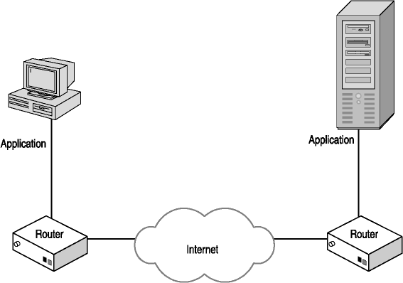
Figure 2-1. Communications across the Internet
This routing of information requires that all computers follow the same set of rules for creating and handling packets, but have the flexibility to support a number of different transmission needs, such as different maximum frame sizes.
The information being passed from the source computer to the destination computer might also be confidential in nature. Although each router along the path must be able to read the addressing information, there must be a way to secure the data being transported so that only the destination computer can receive and interpret the information being sent by the source computer.
After this lesson, you will be able to
-
Map the TCP/IP protocol suite to the seven layer Open Systems Interconnection (OSI) communication model
-
Identify the fields of the IP header
-
Explain what packet encapsulation is
-
Explain the process of fragmentation and reassembly
Estimated lesson time: 45 minutes
What Is TCP/IP?
TCP/IP is the suite of protocols used to communicate on the Internet. Each protocol of the TCP/IP protocol suite is associated with a layer of the seven-layer OSI communications model, which is an International Organization for Standardization standard. The seven layers are the Physical layer, Data Link layer, Network layer, Transport layer, Session Layer, Presentation Layer, and the Application layer. The TCP/IP protocols are shown with their respective layers in Figure 2-2.
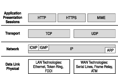
Figure 2-2. OSI seven-layer presentation model for TCP/IP
Each layer of the protocol stack has a particular function when communications occurs between two computers:
- Physical layer.
The Physical layer (Layer 1) is typically implemented in hardware and is responsible for placing data bits on and receiving bits from the communications media, such as coaxial cable.
- Data Link layer.
The Data Link layer (Layer 2) is responsible for converting data packets that are received from the network layer and encoding them into bits. It is also responsible for accepting bits from the physical layer and converting them into data packets. The data packets that are formed into groups of bits are known as frames. This layer is divided into two sub-layers: the Media Access layer (MAC) and the Logical Link Control layer (LLC). The MAC sub-layer controls how a computer on a network gains access to the data, and permission to transmit that data on the network. The LLC sub-layer manages frame synchronization, error checking, and flow control.
- Network layer.
The Network layer (Layer 3) provides routing and switching capabilities, and creates logical paths between two computers to create virtual circuits. This layer is responsible for routing, forwarding, addressing, internetworking, error handling, congestion control, and packet sequencing. When packets are received from the Transport layer, the Network layer is responsible for ensuring that the packet is small enough to be a valid packet on the underlying network. If the packet is too large, this layer breaks the packet into several packets, and on the receiving computer, this layer places the packets in the proper sequence to reassemble the packet. If the interconnecting devices cannot handle the amount of traffic being generated, this layer also provides congestion control.
- Transport layer.
The Transport layer (Layer 4) transfers data between end systems or hosts, and is responsible for end-to-end error recovery and flow control between the two end systems. This layer ensures complete data transfer between the two systems.
- Session layer.
The Session layer (Layer 5) establishes, manages, and terminates connections between applications on two computers. The session layer sets up, coordinates, and terminates all interchanges between applications on both computers. This layer manages session and connection coordination.
- Presentation layer.
The Presentation layer (Layer 6) provides a heterogeneous operating environment by translating from the application's data format to the underlying network's communications format. This layer is also known as the syntax layer.
- Application layer.
The Application layer (Layer 7) support end-user and application processes. Communication partners and quality of service levels are identified, user authentication and privacy considered, and any constraints on data syntax identified.
The Internet Protocol (IP) operates at the Network layer. The Internet relies on the services provided by IP to fragment and route IP datagrams from source computer to destination computer, regardless of the physical network the two computers are on. For IP networks, a datagram is a portion of a message transmitted over a packet-switching network. The current version of IP used on the Internet is version 4 (IPv4). A list of IP versions can be found at the Internet Assigned Numbers Authority (IANA) Web site at http://www.iana.org/assignments/version-numbers.
Many attacks that occur take advantage of the Internet layer to compromise your defenses and break the confidentiality-integrity-availability (C-I-A) triad, whereas others attack protocols at the Transport and Application layers. To effectively defend against attacks, you must understand what information is available at each layer of the four-layer DARPA communication model, which we discuss next, as well as how the attacks are occurring, which is discussed in Lesson 2.
Reviewing the Four-Layer DARPA Model
The four-layer DARPA model is a collection of protocols that was originally developed in 1968 by BBN Technologies, which was hired by the Defense Advanced Research Projects Agency (DARPA) to establish a packet switched network between research institutions in the United States. At the time, functionality and performance were of greater concern than security. Rather than breaking communications into seven layers, as the International Organization for Standardization (ISO) Open Systems Interconnection (OSI) model specifies, the DARPA model presents four layers. Figure 2-3 shows the general mapping between the four-layer DARPA model and the seven-layer OSI model.
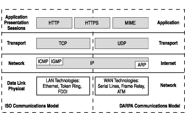
Figure 2-3. Comparing the DARPA communications model to the OSI communications model
- Application layer.
The Application layer is the top layer. Protocols, such as Domain Name System (DNS), File Transfer Protocol (FTP), Simple Mail Transfer Protocol (SMTP), or HTTP use the TCP/IP protocol suite to identify and communicate with other computers. The application typically has the name of the destination computer and relies on another service that operates at the Application layer to identify the IP address of the destination.
Once the IP address of the destination is known, a request (in the form of a packet) is formed, containing detailed information. This is passed to the next lower layer in the DARPA model.
- Transport layer.
When a request from the Application layer is received by the Transport layer, the Application layer request includes information that determines which of these Transport layer protocols will be used.
UDP provides connectionless, unreliable communications, whereas TCP provides connection-oriented, reliable delivery of the information to the destination.
UDP communications is referred to as unreliable, which means that the datagrams are sent without sequencing or acknowledgment, and the Application layer is responsible for recovering or resending lost datagrams.
A request is formed and passed to the next lower layer in the DARPA model.
- Internet layer.
The Internet layer is responsible for routing packets between networks. IP is a routable protocol that provides the functions necessary to deliver a package of bits from a source to a destination. The request that is formed at this level is a packet of bits known as a datagram. IP provides for transmitting datagrams from sources to destinations, and for fragmentation and reassembly of long datagrams, if necessary, for transmission through "small packet" networks.
A request is formed and passed to the next lower layer in the DARPA model.
- Network Interface layer.
The Network Interface layer is used for communicating with other computers. When a packet is sent from the source computer to the destination computer, the Internet layer determines whether the system is on the local network or on a remote network.
-
If the destination is local, the Network Interface layer uses the ARP protocol to determine the media access control (MAC) address of the destination computer's network interface card, creates a frame header, uses the information passed down from the Internet layer as the payload, creates a preamble, and then pushes the completed packet on to the wire. A frame header is control information added by protocols at this layer. The payload is the packet presented to this layer from the Internet layer.
-
If the destination is remote, the Network Interface layer uses the ARP protocol to determine the MAC address of the designated default gateway, creates a frame header, uses the information in the datagram as the payload, creates a preamble, and then pushes the completed packet on to the wire, where the default gateway sends the packet to an upstream router.
-
Reviewing the TCP/IP Communications Flow
Any time one computer needs to communicate with another, a sequence of steps is followed. For this example, we relate Web browsing to the TCP/IP communications flow.
When a user at a computer wants to access a Web page, he or she typically starts a Web browser application and types the name of the Web site he or she wishes to visit. The browser generates a request to have the Web site name resolved to an IP address. The browser then attempts to establish communications with that Web site.
The information that is passed from the upper layers of the DARPA model to the lower layers is packaged for delivery by each necessary protocol as it goes down through the TCP/IP stack. When the datagram reaches the destination, the packet is passed up the TCP/IP stack and the process is reversed. Figure 2-4 represents this communications process.
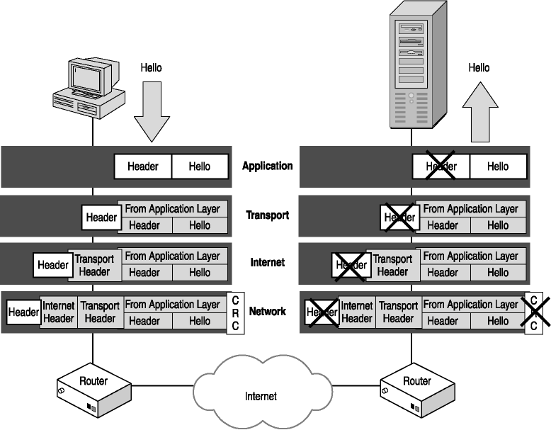
Figure 2-4. Following communications from a source computer to a destination computer
When application data is sent from one computer to another:
-
The information is passed from the Application layer to the Transport layer.
-
The Transport layer protocols consider the Application layer information as the payload (or data) that needs to be delivered and create a header that contains information such as source and destination port, to help with delivery of the information to the destination computer. That information is passed to the Internet layer.
-
The Internet layer protocols considers the Transport layer information as the payload that needs to be delivered and create an IP header that contains information such as destination IP addresses, to help with delivery of the datagram to the destination computer. That information is passed to the Network Interface layer.
-
The Network Interface layer protocols consider the Internet layer information as the payload that needs to be delivered and creates a preamble and a frame header, which contains the source and destination MAC addresses, to help with delivery of the datagram to a destination on the local network once it arrives, and trailer information, called a checksum that contains the count of the number of bits in a transmission so that the receiver can ensure the packet did not get damaged in transit. A checksum is an error detection method that is used to determine if a single bit error occurred in transmission. The information is placed on the local network.
-
When the information reaches the destination computer, the Network Interface layer protocols strip the preamble and checksum from the packets and then pass the payload to the Internet layer.
-
The Internet layer protocols strip the IP header from the packet and pass the payload to the Transport layer.
-
The Transport layer protocol strips the TCP or UDP header and passes the payload to the Application layer.
-
The application that is specified to manage that data receives the data.
Understanding Network Interface Frames
When the Network Interface layer creates an information packet, or frame, to place on the network, there are three general components to the packet: the header, the payload, and the Frame Check Sequence (FCS).
The payload is the information provided by the Internet layer, whereas the header and FCS (also known as the trailer) are created by the Network Interface layer. There are a number of local area network (LAN) protocols that can be used on a network, and each has a different header and trailer structure.
Knowing the LAN technology that is in use allows a hacker to identify the local source and destination addresses and determine what bits of the packet represent the payload. This information can be used to disrupt the C-I-A triad.
Header
Header information differs with different LAN technologies, but there are some things that are always contained in the header. There is always a preamble, or some other sequence of bits that identify the start of a valid frame. All Network Interface layer headers also have fields for the destination and source MAC address. For instance, Ethernet II header packets contain a series of alternating ones and zeros that is 7 bytes long, followed by the bit sequence 10101011. This signals the beginning of a valid Ethernet II packet, and the 6 bytes of data following are the destination MAC address. Figure 2-5 shows an Ethernet II header.
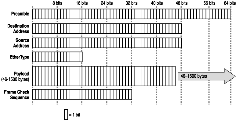
Figure 2-5. An Ethernet II header
Payload
The payload is the information that is passed from the application through the Transport and Internet layers to the Network Interface layer. For the Network Interface layer, the payload must be encapsulated in a packet with a header and trailer and then placed on the wire.
The maximum size of a payload varies for various LAN technologies. For instance, the maximum size of an Ethernet II payload is approximately 1500 bytes, whereas the maximum payload for an Asynchronous Transfer Mode (ATM) frame is approximately 48 bytes.
Frame Check Sequence
The FCS is also called a cyclic redundancy check (CRC) and provides a bit-level integrity check for the packet. This ensures that the packet arrived without transmission-related damage. The CRC is generated using an algorithm on the bits that comprise some or all of the fields at the source. When the destination computer receives the packet, the same algorithm is used to verify that the packet was not damaged in transit.
More information about the CRC used in network layer communications can be found at the International Telecommunication Union (ITU) Web site at http://www.itu.int.
Understanding IP Datagrams
There are two general components to the IP datagram: the header and the payload. Much like the packet created by the Network Interface layer, when IP is used to form a datagram, there is a structure to the packet that can be recognized by every implementation of TCP/IP in use. This allows any computer running any operating system to communicate with any other computer, as long as both are using the same version of the TCP/IP protocol suite.
Because TCP/IP is an industry-standard protocol and every implementation of TCP/IP can decode the header information of an IP datagram, every hacker and cracker can identify that same information and use it to compromise your C-I-A triad.
Exploring the IP Header
The header portion of an IP packet contains information that is used to determine the characteristics of the packet, the destination and source addresses, whether the datagram is one of several packets, and what protocol is in use.
Although the size of an IP header can vary, it is defined in industry standards. Therefore hackers and crackers are able to sniff a packet on networks, including the Internet, and read the information. Understanding the information that is presented in an IP packet will help you understand how the integrity of the information you send across a local network or the Internet can be compromised. Figure 2-6 shows an IP datagram header. A brief explanation of each field follows.
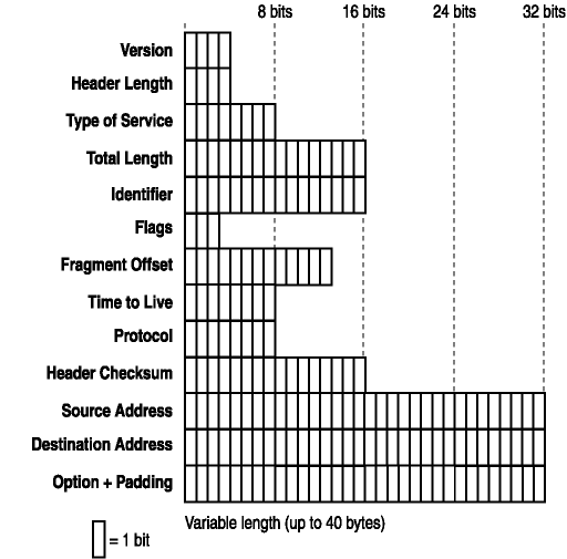
Figure 2-6. An IP datagram header
- Version (4 bits).
The Version field is used to identify the IP version of the packet. IPv4 is the current version in use on the Internet, but there are IPv6 stacks available for most operating systems in use today.
- Internet Header Length (4 bits).
The Header Length field identifies how large the IP header is. The field specifies the length of the header in 32-bit words (4-byte blocks) and points to the beginning of the payload. The header defines the length in number of bytes, and the valid numbers range from 5 to 15. This means the header length can range from 20 bytes to 60 bytes in length.
- Type of Service (8 bits).
This field is used to define the parameters for the type of service desired. Service levels that can be requested as a packet travels from the source computer to the destination computer include levels of priority, delay, throughput, and reliability.
- Total Length (16 bits).
This is the total length of the datagram (measured in bytes), and includes both the header and payload. When you read the RFC defining the IP datagram (see RFC 791), you will notice it states that this field is measured in octets. An octet is 8 bits in length, which is a byte. The maximum size of a valid IP datagram is 65,535 bytes, although the RFC-recommended size is 576 bytes, which allows for a 64-byte header and a 512-byte payload.
- Identifier (16 bits).
This value is set by the sender and is used for reassembly of fragmented IP datagrams at the destination.
- Flags (3 bits).
These bits are used to indicate whether an IP datagram can be fragmented, and if so, if it is the last fragment. IP fragmentation is covered in more depth later in this chapter.
- Fragment Offset (13 bits).
This field specifies where in the IP datagram this fragment belongs. This is measured in 8-byte (64-bit) increments, and the first fragment always has an offset of 0, because it is the first fragment in the series. The fragment and fragment offset information is extremely important because datagrams do not always reach the destination in order.
- Time-to-Live (8 bits).
The Time-to-Live (TTL) field specifies the maximum number of links a packet can pass through to reach the destination computer. The source computer sets the maximum TTL, and then each router that handles the packet decrements the TTL by 1 and forwards the packet. If the TTL decrements to 0 before reaching the destination, the packet is discarded.
- Protocol (8 bits).
This field specifies the protocol used at the Transport layer of the DARPA four-layer model. For instance, if the datagram is a TCP packet, then this field would be set to 6. If it were a UDP packet, this field would be set to 17. For a complete list of valid protocols, refer to http://www.iana.org/assignments/protocol-numbers.
- Header Checksum (16 bits).
This field is used to provide a bit-level integrity check of the header information. This checksum is for the IP header only and does not include the IP payload portion of the datagram. The source computer calculates the initial checksum before the packet is sent. As each router receives the packet, the checksum is verified, the TTL is decremented, a new checksum is calculated, and the packet is forwarded. If the checksum is incorrect at any router between the source and destination computer, the datagram is discarded.
- Source IP Address (32 bits).
This is the IP address of the source computer.
- Destination IP Address (32 bits).
This is the IP address of the destination computer.
- IP Options and Padding (variable).
This field is optional and can vary in length. If this field is used, it must be added in increments of 32 bits. That is, if the datagram has one option (defined in 8 bits), an additional 24 bits (all zeroes) must be added as padding. Thus the added option will add 32 bits (4 bytes) to the overall length of the IP header. Each option is defined in 8 bits, and has three fields: a 1-bit copied flag, a 2-bit option class, and a 5-bit option number. More information about options can be found at http://www.iana.org/assignments/ip-parameters.
Payload
The payload is the packet that is provided by the Transport layer. This packet includes the Application layer data, which is added to a Transport layer packet for delivery to the destination computer.
The size of the payload can vary greatly, because the IP protocol allows an overall IP datagram size of up to 65,535 bytes, but can be as small as approximately 600 bytes.
Reviewing ICMP Header Fields
The ICMP protocol reports errors and control conditions on behalf of the IP protocol. This is because the IP protocol provides end-to-end datagram delivery capabilities, but is not designed to be absolutely reliable. Figure 2-7 shows an ICMP header. A brief explanation of each field follows.
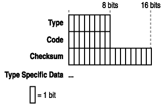
Figure 2-7. ICMP message structure and header fields
The ICMP message is encapsulated in an IP datagram. As with the IP datagram, there is a Network Interface layer header and trailer, and an IP header. With those are the ICMP header and ICMP message data. The ICMP header fields can vary, but always have the following fields:
- Type (8 bits).
This field specifies the format of the ICMP message. This includes Echo Request, Echo Reply, Source Quench, Parameter Problem, and so forth.
A complete list of ICMP parameters for the Type field is available at http://www.iana.org/assignments/icmp-parameters.
- Code (8 bits).
This field further qualifies ICMP message within an ICMP type. When combined with the ICMP type, it can identify the specific ICMP message. For instance, if the type field is 3 (destination unreachable), and the code is 1 (host unreachable), that would indicate that the network was reachable, but the host was not. The specific fields for each type field are listed in the ICMP parameters document listed in the preceding note.
- Checksum (16 bits).
This field provides a checksum for the ICMP message. The algorithm used for this checksum is the same algorithm used for the IP header.
- Optional Data.
This field is an optional data field that can be used by the ICMP type.
Reviewing IGMP Header Fields
The IGMP protocol provides multicast or one-to-many datagram delivery. For instance, if you want to send the same datagram to 100 computers, you would use the IGMP protocol to send the message. With IP, you would have to send 100 separate datagrams to accomplish the same task.
To receive multicast datagrams, a computer must inform the router it uses to forward multicast traffic. This is accomplished by sending a host membership report, an IGMP protocol message that a computer sends to the router it is configured to use requesting that multicast messages be forwarded. Once the router receives the report, it forwards multicast datagrams.
A host membership query is an IGMP protocol datagram that a router sends at intervals to verify that computers on a segment are still listening for multicast traffic. Figure 2-8 shows the IGMP message structure.
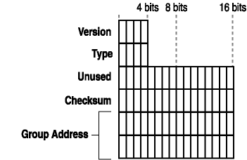
Figure 2-8. IGMP message structure
Like ICMP, the IGMP message is encapsulated in an IP datagram. As with the IP datagram, there is a Network Interface layer header and trailer, and an IP header. With those is the IGMP message data. There are different versions of IGMP, and each has different header information.
For IGMP version 1 (IGMPv1), the header has the following fields:
- Version (4 bits).
This field indicates the version of IGMP that is in use.
- Type (4 bits).
This field indicates the type of IGMP message.
- Unused (8 bits).
This field is unused. The sender blanks the field and the receiver ignores the field.
- Checksum (16 bits).
The checksum is the 16-bit one's complement of the one's complement sum of the 8-byte IGMP message. When the checksum is computed, the checksum field should first be set to 0. When the data packet is transmitted, the checksum is computed and inserted into this field. When the data packet is received, the checksum is again computed and verified against the checksum field. If the two checksums do not match then an error has occurred.
- Group Address (32 bits).
In a Host Membership Query message, the group address field is zeroed when sent, ignored when received. In a Host Membership Report message, the group address field holds the IP host group address of the group being reported. For IGMP version 2 (IGMPv2), the header has the following fields:
- Type (8 bits).
This field indicates the type of IGMP message and is a combination of the version and type fields that IGMPv1 identifies.
- Maximum Response Time (8 bits).
The Max Response Time field is used only in Membership Query messages. It specifies the maximum allowed time before sending a responding report in units of 1/10 second. In all other messages, it is set to zero by the sender and ignored by receivers.
Varying this setting allows IGMPv2 routers to tune the "leave latency" (the time between the moment the last host leaves a group and when the routing protocol is notified that there are no more members). It also allows tuning of the amount of IGMP burst traffic on a subnet.
- Checksum (16 bits).
The 16-bit one's complement of the one's complement sum of the IGMP message, starting with the IGMP Type field. For computing the checksum, the checksum field should first be set to 0. When the data packet is transmitted, the checksum is computed and inserted into this field. When the data packet is received, the checksum is again computed and verified against the checksum field. If the two checksums do not match then an error has occurred.
- Group Address (32 bits).
In a Membership Query message, this field is set to zero when sending a General Query, and set to the group address being queried when sending a Group-Specific Query. In a Membership Report or Leave Group message, this field holds the IP multicast group address of the group being reported or left.
Understanding Fragmentation
Different networks support different maximum-sized frames of information. For this reason, an IP datagram might need to be split into several datagrams for transmission and then reassembled at the destination computer. Fragmentation is breaking a single IP datagram into several smaller datagrams for transport across "small-packet" networks. This allows packets to travel from a source computer to a destination computer across various types of networks. Figure 2-9 shows an IP datagram being fragmented into three datagrams in the following way:
-
The TCP datagram is packaged into a frame.
-
A frame is placed on the local network.
-
An intermediary router fragments the datagram into three fragments.
-
Three fragments are received by the destination computer.
-
Destination computer reassembles the three fragments using information in the header.
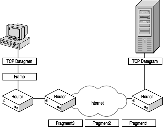
Figure 2-9. Fragmenting an IP datagram
In Figure 2-9, an IP datagram is transmitted on a network that supports a maximum packet size of 4352 bytes to a router that connects to the destination computer's network. The maximum packet size supported on that network is 1492 bytes. The actual size of the packet is 1600 bytes, so it must be fragmented before it can be sent to the destination computer.
When the router receives the IP datagram, it divides the payload of the IP datagram into two pieces, and then adds a header to each. The header contains information that allows the destination computer to recognize the packet is fragmented and to reassemble the IP payload information when both datagrams are received.
Understanding Transport Layer Communications
The UDP and TCP protocols are used at the Transport layer of the four-layer DARPA communications model. Understanding the header information for the Transport layer protocols and how each initiates communications will help you understand how hackers and crackers take advantage of that information to compromise your C-I-A triad.
When one computer communicates with another, applications must be running on both computers to send and receive the data. The UDP and TCP protocols provide a procedure that the applications use to accomplish this communication. Two pieces of information that allow computers to communicate are the IP address and the port address. The destination IP address identifies the destination computer, and the destination port helps identify the application that will receive the information.
Reviewing User Datagram Protocol and its Header Fields
Assigned port numbers for well-known ports, registered ports, dynamic ports, and private ports can be found at http://www.iana.org/cgi-bin/sys-port-number.pl.
The UDP protocol is connectionless; therefore there is no handshake with the destination computer to establish communications before transmitting data to the destination computer. Examples of Application layer protocols that communicate using the UDP protocol are DNS and Trivial File Transfer Protocol (TFTP). The header fields that are defined in the UDP header are as follows:
- Source Port (16 bits).
This is an optional field that indicates the port of the sending process. It is optional because the sender is not establishing communication to the destination, rather it is sending a message.
- Destination Port (16 bits).
This field identifies the port that will receive the data on the destination computer.
- Length (16 bits).
This field indicates the length in octets of the datagram, including the UDP header and data.
- Checksum (16 bits).
This field provides a checksum for the UDP message. The algorithm used for this checksum is the same algorithm used for the IP header. The checksum is calculated including the UDP pseudo-header. The pseudo-header is created and conceptually prefixed to the UDP header and is used to help protect against misrouted datagrams. It is a pseudo-header because it is not actually sent with the datagram.
Reviewing the Transmission Control Protocol and its Header Fields
The TCP protocol is connection-oriented, which means that the source and destination computer establish a connection and then transfer data. This ensures reliable delivery of the data to the destination computer. TCP also supports bytestream, which means the data from the Application layer is segmented into datagrams that the source and destination computers will support, and then reassembled at the destination computer. The TCP header structure has the following fields:
- Source Port (16 bits).
This field indicates the Application layer protocol that is sending the TCP segment. It is combined with the IP address to create a socket, a unique identifier that acts as an endpoint in a connection because it defines the computer and Application layer protocol in the top layer of the TCP/IP stack that will manage the communications between two computers.
- Destination Port (16 bits).
This field indicates the Application layer protocol for the destination computer.
- Sequence Number (32 bits).
This field represents the first data octet of the segment. Because TCP supports bytestream communications, the Application layer is responsible for reassembling the incoming TCP segments.
- Acknowledgement Number (32 bits).
This field specifies the value of the next sequence number the sender of the segment is expecting to receive.
- Data Offset (4 bits).
This field indicates where the TCP segment data begins and is used when the segments are reassembled.
- Reserved (6 bits).
These are reserved for future use and must be set to 0.
- Flags (6 bits).
This field provides the control bits, also called TCP flags.
The TCP flags are defined in RFC 3168, and Internet Official Protocol Standards document STD0007. - Window (16 bits).
This indicates the number of data octets that the sender of the segment is willing to accept, which is the available receive buffer size.
- Checksum (16 bits).
This field provides a checksum for the UDP message. The algorithm used for this checksum is the same algorithm used for the IP header.
- Urgent Pointer (16 bits).
This field indicates the location of urgent data in the segment. This field is only used if the control bits are set to Urgent Pointer field significant (URG).
- Options and Padding (variable).
One or more TCP options can be added to the TCP header.
The TCP Three-Way Handshake
To establish TCP communications, two computers use a three-way handshake, as shown in Figure 2-10. The handshake process uses the information in the header to establish a communications link between the two computers that will provide reliable data transfer.
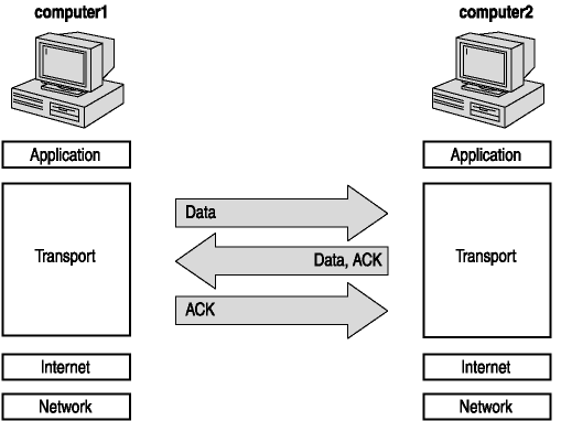
Figure 2-10. TCP three-way handshake
With the three-way handshake the two computers that are establishing communications set a starting sequence number for the data being sent, the size of the receive buffer, the maximum segment size, and the TCP options supported. For this example, computer1 is establishing communications with computer2. The three segments that are used to establish communications are as follows:
- SYN segment.
This is the first segment of the three-way handshake. The information sent by computer1 includes source and destination port, starting sequence number, the receive buffer size, maximum TCP segment size, and the supported TCP options.
- SYN-ACK segment.
This segment is the reply that computer2 returns to computer1. The information sent includes source and destination port, starting sequence number, acknowledgment number, receive buffer size, maximum TCP segment size, and an acknowledgment that computer2 supports the options that computer1 sends. When computer2 sends this message, it reserves resources to support this connection.
- ACK segment.
This segment is sent by computer1 to establish the final TCP connection parameters that will be used between the two computers. The information sent includes the source and destination ports, sequence number, acknowledgment number, ACK flags, and window size.
Once the handshake is complete, both computers recognize how communications will occur, what the starting sequence number is, what limitations exist for packet size, and what TCP options are supported. They are then ready to begin data transfer.

In this exercise, place the steps in the order they would occur if you were connecting to a Web page from your home computer.
-
The Network Interface layer protocols consider the Internet layer information as the payload (or data) that needs to be delivered and they create header information to help with delivery of the datagram to a destination on the local network, as well as trailer information that is used to ensure the packet did not get damaged in transit. That information is placed on the local network.
-
The Transport layer protocol strips the header and trailer information and passes the payload to the Application layer.
-
The Internet layer protocols consider the Transport layer information as the payload (or data) that needs to be delivered and they create header information to help with delivery of the datagram to the destination. That information is passed to the Network Interface layer.
-
The Internet layer protocols strip the header and trailer information from the packet, and pass the payload to the Transport layer.
-
The application that is specified to manage that data receives the data.
-
An application is started that needs to connect to a server and retrieve information. A message is created and passed from the Application layer to the Transport layer.
-
The Network Interface layer protocols strip the header and trailer information from the datagram and pass the payload to the Internet layer.
-
The Transport layer protocols consider the Application layer information as the payload (or data) that needs to be delivered and they create header information to help with delivery of the information to the destination. That information is passed to the Internet layer.
In this exercise, you will view and identify information captured using Microsoft Network Monitor on a system running the Microsoft Windows XP operating system. Figure 2-11 shows the results of a network capture when viewing the home page at http://www.ietf.org.
Refer to Figure 2-11 and provide the missing information in the list below.
-
Ethernet frame length: ____________________
-
IP version: ____________________
-
Application-level protocol in use: ____________________
-
First octet of the source IP address: ____________________
-
First octet of the destination IP address: ____________________
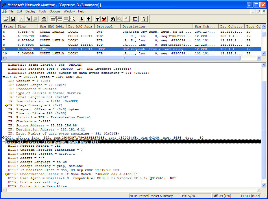
Figure 2-11. A Network Monitor capture file
If you have a system connected to the Internet, and you are either at home connecting to an ISP or have explicit, written permission to capture network traffic, you can capture network traffic and use your capture file to identify the information listed above. Follow the steps listed below to duplicate the results displayed in Figure 2-11, using your network monitor.
-
Flush the DNS look-up cache (if applicable for your operating system). For instance, if you are running Windows XP, you type ipconfig /flushdns at the command prompt.
-
Start a network monitor capture.
-
Open a Web browser. Go to http://www.ietf.org and view the home page.
-
After returning to the home page configured in your Web browser, close the Web browser.
-
Stop the network monitor capture.
-
View the captured data.

The following questions are intended to reinforce key information presented in this lesson. If you are unable to answer a question, review the lesson and then try the question again. Answers to the questions can be found in Appendix A, "Questions and Answers."
-
After each layer of the DARPA communications model shown below, list the TCP/IP protocols that the particular layer uses.
Application Layer
Transport Layer
Internet Layer
Network Interface Layer
-
Place the following TCP/IP communications steps in the correct order:
-
The IP protocol adds a header to the packet and passes the packet to the next lower layer.
-
The Transport layer protocol adds a header to the Application layer request and passes the packet to the next lower layer.
-
The network interface adds header and trailer information to the packet and places it on the network.
-
An application is started that requests communications with a computer on the network. The application forms a packet and passes the request to the next lower layer.
-
The Transport layer strips the header and passes the packet to the next higher layer.
-
The Network Interface layer receives the packet from the network, strips the header and trailer information, and passes the packet to the next higher layer.
-
The Internet layer strips the header and passes the packet to the next higher layer.
-
The Application layer strips the header and passes the information to the application.
-
-
What protocol and field store the address of the destination computer?
-
The source address of the Ethernet II frame
-
The destination address of the Ethernet II frame
-
The source address of the IP datagram
-
The destination address of the IP datagram
-
-
Which header contains a field that specifies the total size of a frame?
-
Transport layer header
-
Internet layer header
-
Network Interface layer header
-
All of the above
-
Lesson Summary
In this lesson, you reviewed the four layers of the DARPA communications model, associated the TCP/IP protocol suite to those layers, and identified the various fields of an IP header. Specifically, you should understand the following:
-
The four layers in the DARPA communications model are the Application layer, Transport layer, Internet layer, and the Network Interface layer.
-
Applications operate at the Application layer and typically when two computers communicate, they both have an application that can interpret the communication packets sent by the other computer.
-
The Transport layer supports the TCP and UDP protocols. UDP provides efficient communications, but TCP provides reliable, connection-oriented communications.
-
The IP, ICMP, and IGMP protocols operate at the Internet layer of the DARPA communication model. The IP address header contains the source and destination computer IP addresses and identifies the Transport layer protocol of the datagram.
-
The Network Interface layer is responsible for actually placing the packet on the network. The header information added at this layer provides the MAC address of the source and local network destination computer.
-
The fields of the header information at the Transport, Internet, and Network Interface layers can all vary in length, but are all well-defined and the information in the header can be interpreted by any application that understands IP header information.
EAN: 2147483647
Pages: 55