Lesson 3: Cables and Connectors
Cables and connectors are critical to the operation of any computer peripherals. A computer professional must be able to identify and understand the various types of cables and connectors. This lesson discusses common connectors and their functions.
After this lesson, you will be able to:Estimated lesson time: 20 minutes
- Identify cables and connectors by their names and functions.
Parallel Printer Cables
Parallel printer ports and cables are used to connect printers and other add-on items such as CD-ROMs, tape drives, and scanners. Centronics Corporation invented the most common type. It is an 8-bit parallel connection with handshaking signals between the printer and the computer—these tell the computer when to start or stop sending data. A standard printer cable is configured with a 36-pin Centronics connector on the printer end and a standard 25-pin "D" (male) on the computer end. A standard 25-pin "D" (female) connector found on the back of the computer designates it as a parallel port. (See Figure 12.8.)
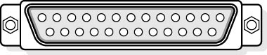
Figure 12.8 Standard 25-pin D connector
The original parallel port was designed only to send information to printers and was unidirectional. However, some bidirectional communication was possible by manipulating the handshaking lines. Today, computer manufacturers have developed updated versions that allow better bidirectional communication while maintaining the original Centronics specification. The Institute of Electrical and Electronic Engineers (IEEE, pronounced "I triple E") developed a standard—IEEE 1284—to oversee the standardization of these ports.
There are three bidirectional standards used today:
- Bi-Tronics: This modified Centronics connection was created by Hewlett-Packard. It utilizes bidirectional communication, allowing the printer to send messages to the computer (out of paper, paper jam, and so forth).
- EPP (enhanced parallel port): This features 2 MB per second data transfer rates, bidirectional 8-bit operation, and addressing to support multiple (daisy-chained) peripherals on a single computer.
- ECP (extended capabilities port): This was developed by Hewlett-Packard and Microsoft. It features 2 MB per second data transfer and bidirectional 8-bit operation. ECP will specify whether transmitted information consists of data or commands for the peripheral. ECP supports CD-ROM and scanner connections, RLE (Run Length Encoded) data compression, and DMA support to increase transfer speed and reduce processor overhead.
NOTE
The EPP and ECP standards often have to be enabled in the CMOS setup before the specified port can use them.
IEEE 1284 Printer Modes
A vast array of printers is available, and in order to ensure that you are obtaining optimum performance, the printer, the printer driver, and the software using the printer must be configured for the same mode. The following table describes various printing modes and their capabilities.
| Mode | Capabilities | Speed | Notes |
|---|---|---|---|
| Compatibility | 8-bit output. Hardware handshaking. No DMA. | 100-200-KB per second out | Original parallel port |
| 4-bit | 4-bit input using some of the printer's handshaking lines. | 100-200 KB per second out; 40-60 KB per second in | HP Bi-Tronics mode |
| 8-bit | 8-bit I/O bidirectional. | 80-300 KB per second | Original bidirectional port |
| ECP | 8-bit I/O. Can use DMA. | >2 MB per second | Scanners and high-speed printers |
| EPP | 8-bit I/O. | Up to 2 MB per second | Very flexible modes of operation |
Parallel Pin Assignments
Just like modem cables, it is important for printer cables to have the correct pin connections. The following table describes the standard parallel pin assignments for the computer-end (25-pin) and the printer-end (Centronics) connectors.
| Computer | Direction of Data Flow | Printer | Name | ID | Function |
|---|---|---|---|---|---|
| 1 | 1 | Strobe | STROBE | Sends data to printer. | |
| 2 | 2 | Data bit 0 | DBO | ||
| 3 | 3 | Data bit 1 | DB1 | ||
| 4 | 4 | Data bit 2 | DB2 | ||
| 5 | 5 | Data bit 3 | DB3 | ||
| 6 | 6 | Data bit 4 | DB4 | ||
| 7 | 7 | Data bit 5 | DB5 | ||
| 8 | 8 | Data bit 6 | DB6 | ||
| 9 | 9 | Data bit 7 | DB7 | ||
| 10 | 10 | Acknowledge | ACK | Printer acknowledges receipt of data. | |
| 11 | 11 | Printer busy | BUSY | ||
| 12 | 12 | Paper error | PE | ||
| 13 | 13 | Select | SLCT | Indicates printer is online. | |
| 14 | 14 | Auto feed | AUTOFD | ||
| 15 | 32 | error | ERROR | ||
| 16 | 31 | Reset | Printer | INIT | |
| 17 | 36 | Select input | SLECT IN | ||
| — | 18 | 5v | 5 volts available from some printers. | ||
| 18-25 | 16, 19-30, 33 | Ground | Sometimes to pin 17. |
Serial Port Cables
A serial port allows a computer to send data over long distances by converting parallel data to serial data. Typical computers will have one or two serial ports, usually designated as COM1 and COM2. The "standard" port is a 9-pin male connector on the computer, shown in Figure 12.9. (There are also 25-pin cables available.)
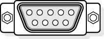
Figure 12.9 Standard 9-pin D connector
The following table describes the pin connection for the 9-pin and 25-pin serial cable connectors.
| 9-pin | 25-pin | Name | ID | Function |
|---|---|---|---|---|
| 1 | Shield | |||
| 3 | 2 | Transmitted Data | TX | Data sent from computer. |
| 2 | 3 | Receive Data | RX | Data sent to computer. |
| 7 | 4 | Request to Send | RTS | Computer is ready to send. |
| 8 | 5 | Clear to Send | CTS | "Other end" is ready to receive |
| 6 | 6 | Data Set Ready | DSR | "Other end" is ready to receive. |
| 5 | 7 | Signal Ground | SG | GND. |
| 1 | 8 | Data Carrier Detected | DCD | The modem has detected a signal from another modem. |
| 4 | 20 | Data Terminal Ready | DTR | Computer is ready to send. |
| 9 | 22 | Ring Indicator | RI | Modem detects line ringing. |
Null-Modem Cables
Null-modem cables are used to directly connect two computers together without the need for a modem. The transmit and receive wires in the cable (wires 2 and 3) are switched to make the computers "think" they are using modems.
SCSI Cables
SCSI cables come in a variety of sizes depending on the type of SCSI used and the manufacturer of the device. Typically, internal cables are flat ribbon types and external cables are shielded bundles.
Keyboard Cables
Another peripheral device with a cable that we encounter and yet never think about is the keyboard. Because there are different types of keyboard cables (and connectors) and because, on occasion, the technician might encounter a problem with a keyboard connector, they are worthy of mention.
Keyboards are manufactured in two different styles with different cables and connectors. Earlier versions used a 5-pin DIN connector (DIN stands for Deutsche Industrie Norm, the German national standards organization), and most new keyboards use a 6-pin DIN connector, the same as is used on a PS/2 mouse. Connectors are available to convert the 5-pin DIN to a 6-pin mini-DIN. Although they have a different number of pins, they use the same wires and pin outs. Data is sent serially to the keyboard using the keyboard interface. Data is written to the controller's input buffer to accomplish this. Keyboard data passes through pin 2 of the connector, while clocking signals move through pin 1. A keyboard reset, which can be connected to the system's reset line, is included at pin 3. Ground and +5-volt DC connections are applied to the keyboard through pins 4 and 5.
Identifying Cables and Connectors
Because printers and modems can both use 9-pin and 25-pin connectors and cables, a computer technician must be able to identify the function of the cables by their connectors. Other devices, such as monitors and game ports, use 15-pin connectors. Cable identification can be confusing, but it is important. The following table summarizes how to identify common cables and connectors.
| Function | Computer Connector | Cable Connector |
|---|---|---|
| Communication (serial) | 9-pin or 25-pin male | 9-pin or 25-pin female |
| Printer (parallel) | 25-pin female | 25-pin male |
| Monitor (VGA and SVGA) | 15-pin female (three rows of pins) | 15-pin male (three rows of pins) |
| Monitor (MGA and CGA) | 9-pin female | 9-pin male |
| Game port (joystick) | 15-pin female (two rows of pins) | 15-pin male (two rows of pins) |
| Keyboard | 5-pin DIN female or 6-pin DIN female (PS/2) | 5-pin DIN male or 6-pin DIN male (PS/2) |
Troubleshooting Cables
Cables and connectors are a very common source of problems. Here are a few suggestions for troubleshooting:
- If a peripheral device doesn't work, always check the cables, especially if the device has been working recently.
- Always check for loose connections.
- Check for bent or broken pins on the connector. Bent pins can sometimes be repaired; however, they will always be susceptible to damage later, because the pin has been weakened. It is a good idea to mark these connectors and use them with care. A better idea is to replace them.
- If a connector or cable doesn't fit or if you have to push hard to make the connection, something is wrong. Either a connector has been damaged or it is not the right match.
- Check for worn or frayed cables. Replace if necessary.
- Make sure you have the right cable. Some, such as null-modem cables, look just like standard communication cables, but will not work with a modem.
- Always be wary of "homemade" cables.
Summary of Connectors
Computers use a large variety of connectors for various peripherals. The following table offers a summary of the most common connectors and their uses.
| Name | Uses |
|---|---|
| DB-9 | Serial ports—external modem, mouse, printer. |
| DB-25 | Parallel port—printer, scanner, removable drive. |
| RJ-11 | Standard telephone connector—2 wires. |
| RJ-12 | Standard telephone connector—4 wires—used with dual phone connections. |
| RJ-45 | Network connector. |
| PS/2 (mini-DIN) | Mouse, scanners. |
| Centronics | Printers. |
| USB | Universal serial bus—Technology that allows multiple peripherals to be attached to one cable. Popular devices are keyboards, mouse devices, modems, video cameras, and Zip drives. |
Lesson Summary
The following points summarize the main elements of this lesson:
- There are many different types of computer cables and connectors. It is important for the computer technician to be able to identify each of them.
- The evolution of a technology often brings modification to cables, the way they are wired, and their length.
- Distinguishing between a male or a female connector is often the key to identifying the connector's function.
- Loose or poorly connected cables are often the cause of computer problems.
EAN: N/A
Pages: 127