Lesson 1: Understanding Expansion Buses
Expansion buses are used to connect devices to the motherboard using the motherboard's data bus. They allow the flow of data between that device and other devices in and connected to the computer. Early computers moved data between devices and the processor at about the same rate as the processor. As processor speeds increased, the movement of data through the bus became a bottleneck. Therefore, the design capability of the buses needed to evolve, too. This lesson discusses that evolution.
After this lesson, you will be able to:Estimated lesson time: 30 minutes
- Identify the different types of expansion buses in a computer.
- Identify the difference between the system bus and the expansion bus.
Development of the Expansion Bus
As discussed earlier in Chapter 4, "The Central Processing Unit," every device in the computer—RAM, the keyboard, network card (NIC), sound card, and so forth—is connected to the external data bus. Expansion slots on the motherboard are standardized connections that allow the installation of devices not soldered to the motherboard. The function of an expansion slot is to provide configuration flexibility when devices are added to a computer.
Whether a device is soldered to the motherboard or connected through an expansion slot, all integrated circuits are regulated by a quartz crystal. The crystal sets the timing for the system, giving all parts access to a common reference point for performing actions. Most CPUs divide the crystal speed by two. (If the CPU has a 33-MHz speed, a 66-MHz crystal is required.) Every device soldered to the motherboard—keyboard chip, memory controller chip, and so on—is designed to run at the speed (or at half the speed) of the system crystal.
CPU speeds increased as technology improved, while the speeds of expansion cards remained relatively constant. It was not practical to redesign and replace every expansion card each time a new processor was released—this would have been complicated and expensive for manufacturers. (And, of course, the additional expense would have been passed along to the consumer.) The commitment of the industry to maintain backward compatibility further complicated design tasks, because any new technology would have to run the older, slower devices.
To resolve this dilemma, designers have divided the external data bus into two parts:
- System bus: This supports the CPU, RAM, and other motherboard components. The system bus runs at speeds that support the CPU.
- Expansion bus: This supports any add-on devices by means of the expansion slots and runs at a steady rate, based on the specific bus design.
Dividing the bus enhances overall system efficiency. Because the CPU runs off the system clock, upgrading a CPU requires changing only the timing of the system bus, while the existing expansion cards continue to run as before. There is usually a jumper setting that changes the system clock speed to match the CPU. The ability of the motherboard to make this change sets the limit for the processor speed. Next, we take a look at the evolving types of expansion buses.
Industry Standard Architecture (ISA)
The first-generation IBM XT (with the 8088 processor) had an 8-bit external data bus and ran at a speed of 4.77 MHz. These machines were sold with an 8-bit expansion bus (PC bus) that ran at 8.33 MHz (see Figure 10.1).
![]()
Figure 10.1 8-bit PC bus slot
IBM took steps that fueled the rapid development of the personal-computer market. Their engineers framed the PC's design as an open system, using standard, off-the-shelf components. That allowed third-party developers to manufacture cards that could snap into the PC bus. IBM also allowed its competitors to copy the PC bus.
With this move, IBM established the Industry Standard Architecture (ISA) interface, thus generating the market for clones. A host of third-party developers worked to create products that enhanced the basic machine's features and to keep prices much lower for add-ons than competing proprietary systems such as those from Apple. Without this push, the PC market would have grown more slowly and probably would have been limited to businesses with the money to pay for the more expensive products.
IBM wanted to include a new expansion bus—one that would be compatible with previously released devices—with the release of its AT (Advanced Technology) PC, featuring Intel's 80286 16-bit processor. To accomplish this, the designers added a bus that allowed insertion of either an 8-bit card or a 16-bit card. This change resulted in the standard 16-bit ISA slot. This new 16-bit bus officially ran at a top speed of 8.33 MHz, but on some Peripheral Component Interconnect (PCI)-based systems the actual rate for ISA slots proved to be as high as about 10 MHz. (PCI is discussed later in this lesson.)
NOTE
The term "ISA" did not become official until 1990. Therefore, the 8-bit slot is called the XT, and the 16-bit slot is called the AT. When we refer to an ISA slot or an ISA card, we generally mean the 16-bit AT-style interface. The speed of the slots remained at about 7 MHz.
Problems with the ISA Design
The ISA design is one of the most enduring elements of the PC. It can be found on virtually all systems, from the second-generation IBM PC to machines built today. But it suffers from two major shortcomings: lack of speed and compatibility problems stemming from card design.
As CPU performance increased and applications became more powerful, card designers sought an interface that would allow add-on cards to keep up with the need for improved hard drives, display adapters, and similar products.
Expansion cards must make use of system resources in an orderly way, so that they do not conflict with other devices. When demands for these system resources are not coordinated, the system might behave erratically or even fail to boot up. Formerly, ISA cards often used a bewildering array of jumpers and switches to set addresses for memory use or the IRQ locations they would use.
The need to overcome the expansion card's slowness and compatibility problems led to a search for a new, standard expansion card interface—one that everyone could agree on and that would gain user acceptance.
Micro Channel Architecture (MCA)
In 1986, the market came to be dominated by the new 386 machines with their 32-bit architecture. Most PC manufacturers stuck to the same basic ISA design and MS-DOS. Expansion devices based on ISA technology for the 286 AT class machines could be placed in a new 386 clone without problems.
IBM, however, was feeling the pinch of competition from cheaper clones, and sought to retain its dominance in the PC market. IBM designers produced a new version of the PC, the PS/2 (Personal System/2) and created a proprietary expansion bus called Micro Channel Architecture (MCA) as part of the design. Running at 10 MHz, it offered more performance and provided a 32-bit data path. It was also totally incompatible with older ISA cards.
A feature of MCA is its ability to "self-configure" devices. Unlike devices that use technology in which the PC configures itself automatically to work with peripherals such as monitors, modems, and printers, an MCA device always comes with a configuration disk. When installing a new device in an MCA computer, insert the configuration disk (when prompted), and the IRQs, I/O addresses, and DMA channels will be configured automatically. (IRQs, I/O addresses, and DMA channels are discussed in detail in the next lesson.) An MCA bus is shown in Figure 10.2.
The PS/2 never gained enough market share to compete with the 386. MCA cards were few and far between, and more expensive than competing interface designs.
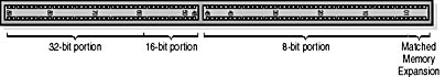
Figure 10.2 MCA bus
MCA is now a lost technology. As a computer technician, you will not encounter MCA on new computers. However, it is still found in some older machines, and you will need to know how to identify it. If a customer brings in a PS/2 machine for service, be sure to obtain the configuration disks for the computer as well as any MCA cards that go with it.
Enhanced ISA (EISA)
In 1988, an industry group answered the challenge of MCA and released a new open standard called Enhanced ISA (EISA—pronounced "ee-suh"). It's a 32-bit, 8-MHz standard.
Unlike MCA, EISA uses a variation of the ISA slot that accepts older ISA cards, with a two-step design that uses a shallow set of pins to attach to ISA cards and a deeper connection for attaching to EISA cards. In other words, ISA cards slip part-way down into the socket; EISA cards seat farther down.
CAUTION
Be very careful to line up cards being placed in an EISA slot precisely and push straight down! If you try to angle the card in, it can be very difficult to seat and you might damage either the connector or the slot.
Although EISA is faster and cheaper than MCA, it never gained much more acceptance than MCA.
Confusion between MCA and EISA technology—along with a limited need for cards that ran at the faster rate and the fact that only a few display, drive controller, and network cards were made available—led to the early demise of both bus technologies. Figures 10.3 and 10.4 show how the slot design of the two technologies differs.
![]()
Figure 10.3 Top view of ISA and EISA bus
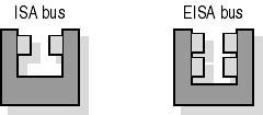
Figure 10.4 Cross section of ISA and EISA bus
VESA Local Bus (VLB)
The problems posed by MCA and EISA designs meant that developers needed an improved bus architecture to speed up graphics adapter performance and keep up with the evolving technologies as new 32-bit operating systems such as Microsoft Windows 3.1 gained popularity. The latter's graphical user interface (GUI) required a much faster display adapter, because every pixel (not just lines of character data) had to be represented and refreshed. About the same time, laser printers and graphics programs like PageMaker and CorelDRAW fostered the "desktop publishing revolution." The hardware industry developed the VESA local bus (VLB) to meet the need for a faster expansion interface. (VESA, the Video Electronics Standards Association, was the driving force behind the new bus technology.) Found only in 386 and 486 machines, the VLB had a short lifespan. The cards based on this design are connected directly to the system-bus side of the PC's external data bus (see Figure 10.5).
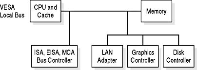
Figure 10.5 VESA local bus design
The speed of the system data bus is based on the clock rate of the motherboard's crystal. During the heyday of the VLB, this was usually 33 MHz, and VLB cards usually ran at half that rate, far outpacing the ISA bus. Some cards ran as fast as 50 MHz, using the full speed of the souped-up system bus. That often caused system crashes, because 50 MHz was outside the VLB specification.
The chip design for the VLB controller was relativity simple, because many of the core instructions were hosted by the ISA circuits already on the motherboard, but the actual data passes were on the same local bus as the one used by the CPU.
The design specification provides two other performance-boosting features: burst mode and bus mastering. In burst mode, VLB devices gain complete control of the external data bus for up to four bus cycles, passing up to 16 bytes (128 bits) of data in a single burst. Bus mastering allows the VLB controller to arbitrate data transfers between the external data bus and up to three VLB devices without assistance from the CPU. This limit of three devices also limited the maximum number of VLB slots to three and called for the use of a coprocessor. Display-system design is covered in more detail in Chapter 11, "The Display System: Monitors and Adapters."
The actual connectors on the motherboard resemble an ISA slot with an additional short slot aligned with it. On systems that support this interface, one to three slots are located on the side of the motherboard closest to the keyboard connection.
Peripheral Component Interconnect (PCI)
Peripheral Component Interconnect (PCI) allows developers to design cards that will work in any PCI-compatible machine. It overcomes the limitations of ISA, EISA, MCA, and VLB, and it offers the performance needed for today's fast systems.
At first glance, there are many similarities between PCI and the older VLB specifications. Both are local bus systems with 32-bit data paths and burst modes. Also, the original PCI design operates at 33 MHz—roughly the same speed as the VLB. But the important differences between them gained PCI its dominant role in expansion-bus technology. These differences stem from the following features:
- The PCI design's special bus and chip set are designed for advanced bus mastering techniques and full arbitration of the PCI local bus. This allows support of more than three slots.
- The PCI bus has its own set of four interrupts, which are mapped to regular IRQs on the system. If a PC has more than four PCI slots, some will be sharing interrupts and IRQs.
NOTE
In Windows 95 or with poorly designed PCI cards (both are becoming rarities), the shared addresses can lead to system conflicts and resource problems. Install PCI cards one at a time to minimize problems. Also, be aware that on many systems not all PCI slots offer full bus mastering. Check the owner's manual for details, especially on machines with more than four slots. In general, the PCI slots closest to the keyboard connector are the best choices for full bus mastering.
- The PCI bus allows multiple bus-mastering devices. Advanced controllers such as SCSI (Small Computer System Interface) cards can incorporate their own internal bus mastering and directly control attached devices, then arbitrate with the PCI bus for data transfers across the system bus.
- Autoconfiguration lets the PC's BIOS assign the IRQ linking the card to the system bus. Most PCI cards have no switches or jumpers to set, speeding installation and preventing many hardware conflicts.
Most PCs on the market today have one or more ISA slot for backward compatibility; however, most expansion cards are now built using the PCI interface. Although Intel was the original driving force behind PCI development, a PCI standards committee maintains the specification, and it is an open design—anyone can design hardware using PCI without being required to pay royalties.
Variations on a Theme: Differences in PCI Versions
The earlier discussion makes PCI sound like a technician's dream interface: fast, reliable, and doing most of the work itself. In most cases, that's true; still, there is always a "but." PCI has gone through many changes, and there are some features to be aware of when you work with one:
- The early PCI motherboards often have jumpers and BIOS settings that must be set to enable proper PCI operation. These are most often found on Pentium 60-MHz and 66-MHz machines.
- The PCI bus speed is not fixed. Newer chip sets can drive it—and the cards on it—at 66 MHz. At full performance, the PCI bus can deliver data transfers at up to 132 MB per second.
- PCI is not used only by PCs. Macintosh and some other non-PC-style computers incorporate PCI. Manufacturers appreciate this feature because it allows them to design core technology and port it to different models, with little effort and using the same production line. Although that's good, you need to be sure that a card is actually designed for the machine you are working on, even if it fits.
Keep in mind that PCI is evolving. That fact will help to keep it a viable interface for the foreseeable future, but it might also lead to incompatibilities between new cards and older machines.
Accelerated Graphics Port (AGP)
In the early days of PCI, the major market for that technology was the high-performance display adapter. The popularity of PCI led to its dominance of the expansion-bus market for card manufacturers. Today, the PCI market includes network cards, sound cards, SCSI adapters, UDMA controllers, and DVD interfaces. That posed a problem for display-card designers: having more cards on a single bus slowed down the performance, just when the increasing popularity of 24-bit graphics and 3D rendering called for greater demands on the display system. The search was on for yet another interface; this time, the solution was a single slot—tuned for the display adapter. Once again, Intel led the way and developed the Accelerated Graphics Port (AGP).
The AGP removes all the display data traffic from the PCI bus and gives that traffic its own 525-MB per second pipe into the system's chip set and, from there, straight to the CPU. It also provides a direct path to the system memory for handling graphics. This procedure is referred to as Direct Memory Execute (DIME). The AGP data path is shown in Figure 10.6.
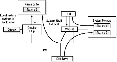
Figure 10.6 AGP Direct Memory Execute offers priority access to display data
The AGP slot, if present, is the only one of its kind on the motherboard and is usually the slot closest to the keyboard connector (see Figure 10.7). It is set forward of the back PC's case than the PCI slots. APG connectors are found only on Pentium II-based and later computers or on similar CPUs from non-Intel vendors.
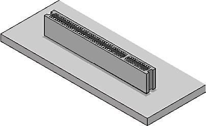
Figure 10.7 An AGP slot on the motherboard
Universal Serial Bus (USB)
The newest addition to the PC bus collection, the universal serial bus (USB) connects external peripherals such as mouse devices, keyboards, joysticks, scanners, and digital cameras to the computer. The USB port is a thin slot; most new motherboards offer two, located near the keyboard. They can also be provided through an expansion card.
USB supports isochronous (time-dependent) and asynchronous (intermittent) data transfers. Isochronous connections transfer data at a guaranteed fixed rate of delivery. This is required for more demanding multimedia applications and devices. Asynchronous data can be transferred whenever there is no isochronous traffic on the bus. USB supports the following data transfer rates, depending on the amount of bus bandwidth a peripheral device requires:
- 1.5 megabits per second (Mbps) for devices, such as a mouse or keyboard, that do not require a large amount of bandwidth.
- 12 Mbps isochronous transfer rate for high-bandwidth devices such as modems, speakers, scanners, and monitors. The guaranteed data-delivery rate provided by isochronous data transfer is required to support the demand of multimedia applications and devices.
USB devices can be attached with the computer running. A new device will usually be recognized by the operating system, and the user will be prompted for drivers, if drivers are required. Bear in mind that USB is a new standard, and some early USB ports and chip sets do not properly support some newer devices. Problems with embedded USB ports are not generally worth repairing. It is usually better to install a new USB interface card.
Lesson Summary
The following points summarize the main elements of this lesson:
- Expansion buses provide a way of connecting devices to the motherboard.
- ISA architecture could accommodate both 8-bit and 16-bit expansion cards.
- MCA was a proprietary architecture for IBM's PS/2 computers.
- EISA 32-bit architecture could accommodate older ISA expansion cards.
- VLB employed burst mode and bus mastering to boost performance.
- PCI architecture makes use of autoconfiguration to let the PC's BIOS assign the IRQ linking the card to the system bus.
- AGP architecture removes display data traffic from the PCI bus.
- USB architecture supports both isochronous (time-dependent) and asynchronous (intermittent) data transfers.
- Expansion buses have changed to keep up with increases in processor speed.
- A computer technician must know how to identify the various expansion buses (ISA, MCA, EISA, PCI, AGP, and USB) to ensure compatibility and know how to maximize performance when upgrading a computer.
EAN: N/A
Pages: 127