Examples
To make these concepts more understandable, let us go through the thinking process in designing databases for a very simple mail-order business, a slightly more complex one, and a set of college courses. Database design is not automatic and obvious, unlike the impression given in textbooks. It generally is an iterative process.
Simple Mail-Order Business
The business for this example sells a set of products described in a catalog. Since most of the business is repeat business, the organization maintains a list of its customers. Customers order products, one at a time, although a customer can have more than one order in the system. The orders can be in different stages: ordered, backorder, in-transit, arrived but unpaid for, and complete. The stage will be called the status. The company wants to keep information on orders around for a long time, perhaps purging them based on the date, so the date is an attribute of an order. The product is shipped to an address the customer has specified, and the bill is handled in a way the customer has specified. In the example, we will not go into the internal details of the shipping or the billing information. These two items of information are part of the customer record. You, the reader, should realize that the description just given for the business could have been different. Billing and/or shipping information should be kept with each order if it is subject to change with each order. Some businesses might not keep a record of customers. The specifications for the particular case help you design the database for that situation.
With the business information in mind, the systems designer decides the following plan. The database will consist of three tables: customers, catalog, and orders. Records in each table will be assigned identification numbers; that is, values that are unique for each record in the table. When you use a DBMS, you typically specify a field as the primary key, the unique identifier for the record. You can let the system assign these values, or you can input them. Social security numbers or driver’s license identification numbers could be used for primary keys, but that is not the approach chosen here. In some cases, two or more fields jointly represent the primary key, and you will read about an example of that situation later in this section.
The customers table holds a record for each customer. A customer record consists of the following fields:
-
Customer identifier
-
Customer name
-
Customer billing information
-
Customer shipping information
The catalog table holds a record for each product. We could have used the name “products” for this table, but since the term catalog connotes something that probably exists at the company, we use it instead. A product record holds the following fields:
-
Product identifier
-
Product name
-
Product cost
-
Product category
-
Product description
The orders table holds information on customer orders. Note that in this system, an order refers to a single product. A customer order consists of the following fields:
-
Order identifier
-
Product identifier for product ordered
-
Customer identifier for the customer making this order
-
Date
-
Quantity
-
Status
The long names for the fields are not typical, but are meant to help you, the reader, understand this example. You probably can infer from the names what data type is indicated. The names are short to medium length character strings; the description and the billing information and shipping information probably require more space. The date is a date, and the cost is given in the currency used by the company. The first two tables are independent of each other. The orders table is different. The product identifier in the product ordered field in the orders table identifies a product. Think of this as a pointer into the catalog table that indicates what product was ordered. Similarly, the customer identifier for the customer making this order indicates the customer by identifier, not by name. The status field in the orders table could be a number, a code, or a description.
The diagram in Figure 5.1 is an entity-relationship diagram for the orders database. The blocks are the entities, and the connecting lines indicate the relationships.
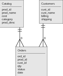
Figure 5.1: Entity-relationship diagram for simple orders.
The names here are fairly arbitrary. Notice that the name of the attribute representing the product id in the orders table is the same as the name in the product table. This is not necessary. However, what is necessary for there to be a relationship between two tables is for a field in the records in one table to refer to records in another table using values that correspond to the primary key.
In the simple mail-order company situation, the diagram indicates that there are three tables; the catalog and customers tables have no relationship to each other. However, each of these two tables is related to the orders table. Each order is for one and only one customer, indicated by the two short horizontal lines near the customer table. This says that the minimum is one and the maximum is one. Similarly, each order is for one and only one product in the catalog table. In contrast, each product can be the subject to zero or one or many orders. This is indicated by the crow’s foot type of symbol with a zero next to it. The crow’s foot indicates many. The same set of symbols is on the line connecting the orders and customers table. How can it be that a customer is responsible for zero orders? The answer is that the business might keep customers in the database even if they never order, or if they did order something at one time and those orders were purged.
Sample Data
To make this example less abstract, Tables 5.1, 5.2, and 5.3 show the fields in three representative tables, capturing the database when there four products, two customers, and five orders. The data is not too realistic, but it should give you an idea of what data in tables can be.
| prod_id | prod_name | cost | category | prod_desc |
|---|---|---|---|---|
| 1 | Bird | 2.50 | Animal | Flapping bird |
| 2 | Crane | 3.00 | Animal | Traditional crane |
| 3 | Box | 1.00 | Box | Magazine cover box |
| 4 | Ornament | 2.00 | Modular | 6-part preliminary bas |
| cust_id | cust_name | billing | shipping |
|---|---|---|---|
| 1 | John Smith | cash | 123 Main Street NY, NY 12345 |
| 2 | Mary Jones | Mastercard XX | 10 Elm Street, apt 23 Town, State 11111 |
| ord_id | prod_id | cust_id | qty | date | status |
|---|---|---|---|---|---|
| 1 | 3 | 2 | 5 | Sept 23, 2002 | Shipped |
| 2 | 1 | 2 | 3 | Sept 23, 2002 | Backordered |
| 3 | 2 | 1 | 3 | Sept 24, 2002 | Shipped |
| 4 | 1 | 1 | 4 | Sept 24, 2002 | Backordered |
| 5 | 4 | 2 | 1 | Sept 25, 2002 | Shipped |
A real database would split up the name into first, last, and middle names, and the address into street number and street, optional apartment, town, state, and zip code. Many Web businesses need provision for addresses out of the United States, so the shipping fields can be quite extensive.
By making use of the information in all three tables, you can derive several facts. For example, Mary Jones has made three orders, two on September 23 and one on September 25. The early orders were for five boxes and three birds; the later order was for one ornament. John Smith has ordered three cranes and four birds on September 24. The crane orders are both on backorder. All other orders, all three of them, have been shipped. The prod_id and the cust_id fields in the orders table are called foreign keys. This is because they refer to primary keys in other tables.
At this point, you, the reader, should do the following exercises: make up a new customer, a new product, and two or three new orders. Make one of the new orders refer to one of the original customers and products, and the other new orders refer to the new customer and/or the new product.
Normalization
The example database design for the mail-order company satisfies the conditions shown in Table 5.4.
| Each field in each table consists of exactly one value, and that value is dependent on the primary key |
| Each field in each table is dependent on the whole primary key |
| Each field in each table is dependent on nothing but the primary key |
Any database design satisfying the first condition is said to be in first normal form; if it satisfies the first and second condition, it is in second normal form, and if it satisfies all three of these conditions in third normal form. The critical term in the second condition is the whole key. This is significant when a primary key is a concatenated key. An example of this will be described later in the chapter. Databases in third normal form are more robust with respect to changes. To demonstrate this, a more complex situation will be described later.
The design and the tables for the mail-order example demonstrate something fundamental about databases with relationships. If you were to remove records in one table, records in another table might point to nonexistent entries. That is, if you remove a product, then all the orders that make reference to that product have meaningless fields. This means that the application must have procedures for deleting records that check for these situations.
Each of the tables in the mail-order example had as a primary key a number that would be produced by the system. Presumably, the DBMS generates unique numbers for each table. This is a common situation, but it is not the only way to get unique values for primary keys. The data in an application can have its own inherent identifier. For example, social security numbers, driver’s license numbers, and passport numbers each exist independent of any computer application. You need to decide what is best for your project.
Physical Database Design
Moving from logical database design to physical database design means that you must plan the implementation. This includes deciding on what aspects of your application are to be computer based and what are to be manual. You need to decide whether you will use databases or files or a combination thereof. You need to specify the nature and size of the fields. Computing systems refer to this as the datatype. In this example, all the id fields are whole numbers to be assigned sequentially by the database management system. Most DBMS do have the facility to do this. The qty field is also a whole number, but not one generated automatically. The cost field would be described as currency, or numbers with two decimal points.
Most DBMS systems have a datatype called Date. Unfortunately, ASP/ JavaScript, Access, MySQL, and PHP have different formats for dates, but we will tackle this problem later.
The product name, product description, shipping, address, and customer name fields are each of the datatypes called character string or string or text. You will need to specify how big to make these fields. You need to weigh the costs in storage space of providing too much room with the danger of having a problem situation if someone comes in with a really long name. Do remember, however, that while you might not be able to control the names of your customers or the size of their addresses, you can control the size of product names and product descriptions.
More Complex Mail-Order Business
Suppose the mail-order store allowed customers to order more than one product at a time. Suppose also that the designer decided to put the cost of each product as part of the order. An order would be:
-
Order id
-
Customer id
-
Any number of sets of product id, quantity, and cost
-
Date
This definition of an order makes sense, but you can see how it would be awkward for a computer system to handle a situation in which the number of values for fields varies. A formal way of saying this is that the design for the more complex mail-order business does not satisfy the first normalization condition in Table 5.4. Certain fields have multiple values. It also does not satisfy the third condition, since the cost field is dependent on the quantity and the cost kept in the product record of the catalog table.
Normalization is a process. The first step in the process is to handle the multiple fields. This is done in a way typical of computing: divide large problems into smaller ones. In place of the single table for orders, define two tables: one for order information that refers to the whole order, and the order for order information that refers to each product ordered. To make this concrete, you can think of it as orders versus product_on_order or order_line. The two tables will be the following:
Orders
-
Order id
-
Customer id
-
Status
-
Date
Product_on_order
-
Order id
-
Product id
-
Quantity
-
Cost
The systems designer could choose to add a product_on_order id to the records. However, the two fields order_id and product_id together do uniquely identify the record and so could be the primary key. This is called a concatenated or composite key. The significance of the second normalization condition now becomes meaningful. If the product_on_order record contained fields such as the product name, then these fields would not be depend on the whole primary key, but just the product id part. If you did put the product names in the product_on_order records, you could have problems. If the name of a product changed, it would be necessary to change all the product_on_orders that mentioned it. The normalization process is to make modifications to make the design in first normal form, and then make modifications to make the design in second normal form.
Continuing with the normalization process, the next step is to consider the third condition in Table 5.4. Are all the fields in each table dependent only on the primary key field of the table? The cost field is suspect. The cost field is dependent on multiplying the quantity of product ordered with the cost per individual item stored back in the catalog table. It may be best to remove it, even though that means the cost for that portion of the order will need to be re-calculated each time. However, if costs are subject to changes and, therefore, considered dependent on orders as opposed to products, it could be appropriate to leave it or take the approach to define yet another table, called bills or invoices.
The underlying principle of database design is to store data in only one place so that you need to change it in only one place. If you have ever had problems dealing with an institution and thought you had settled something, like changing your address, but found that the institution was still using old information, the problem probably arose because of the same data being stored in more than one place.
The ER diagram for the new design is shown in Figure 5.2.
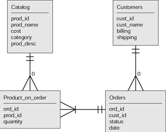
Figure 5.2: Entity relationship diagram for multiproduct orders.
The crow’s foot symbol on the connecting line from product_on_order to orders indicates that each order has at least one product_on_order and potentially many product_on_order records. Each product_on_order relates to exactly one record in the catalog and exactly one record in the orders. If we had not split the orders information into two tables, then the ER diagram would have indicated what is called a many-to-many relationship between orders and the catalog table. Many-to-many relationships are to be changed into one-to-many relationships to ensure a well-defined database.
College Courses
The next example concerns courses at a college. Courses have course numbers, names, and descriptions. Courses might have prerequisites. Courses might be offered in more than one section. A section of a course has a section number, a location, a time, and a teacher. You can put the book down and make a sketch of the ER diagram for this situation.
Figure 5.3 shows a first draft of a design for part of a database for scheduling.
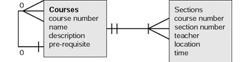
Figure 5.3: Entity-relationship diagram for courses.
The diagram indicates that each course has at least one section. This might not be true—some courses are not offered each term. In fact, this design does not indicate the semester offered. Think about why and how this should be changed.
The prerequisite fields define a relationship between the courses table and itself. Each course can have at most one specified prerequisite, in this design. However, courses can be the prerequisite for more than one course.
Tables 5.5 and 5.6 show representative data for a very small offering of courses.
| Course Number | Name | Description | Prerequisite |
|---|---|---|---|
| CS101 | Computer Basics | Introduction to computer information systems. | None |
| CS120 | Programming Games | Introduction to programming focusing on creating games. Languages are JavaScript and Micromedia Flash ActionScript. | CS101 |
| CS130 | Computer Science I | Introduction to programming. Current language is C++. | CS101 |
| MS130 | Basic Math | Algebra. Probability. | None |
| Course Number | Section Number | Teacher | Time | Location |
|---|---|---|---|---|
| CS101 | 01 | Irina | MW 09-11 | NS3001 |
| CS101 | 02 | Tim | TR 14-16 | NS3001 |
| CS120 | 01 | Irina | M 18-22 | NS1063 |
| CS120 | 02 | Cathy | TR 09-11 | NS1063 |
| CS130 | 01 | Joel | T 18-22 | NS1063 |
| MS130 | 01 | Jim | MTRF 10-11 | NS2001 |
The primary key for the courses is the course number. It is assumed that there is some mechanism apart from the computer application for ensuring that these are unique. The course numbers shown are what are sometimes referred to as coded numbers. They actually are not numbers, but number and letter combinations with both the letters and the numbers having meaning. The letters indicate department, and the numbers, the level. This fragment does not show any 200 or 300 level courses, but presumably there are some. The primary key for the sections table is a concatenated key: the course number and the section number combined. Some institutions would have some coding in the sections numbers indicating evening or weekend sections. You should know that some database professionals argue against such coding because it carries information that tends not to be verified. This is something to think about when you have the task of analyzing and building an application.
The design decisions indicated previously might not be satisfactory for some situations. What if a course required more than one prerequisite? What if the college administration wanted to define different situations regarding the prerequisites; for example, certain prerequisites could be waived with the permission of the instructor (POI); others could be satisfied by a test? When you have discussions with your client to define the implementation of a computer system, you might find yourself in the middle of the formulation of policy. The issues hinted at here seem to indicate that the design should have another table holding prerequisite conditions. A prerequisite record would point to one course as the one that requires another course, and one course as the required course. The prerequisite record would also have a condition field. Figure 5.4 shows the entity-relationship diagram for the application supporting courses and pre-requisites.
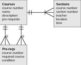
Figure 5.4: Entity-relationship diagram for courses with prerequisites.
The diagram in Figure 5.4 indicates that there are two relationships between the pre-reqs table and the course table. This comes about because there are two fields in the pre-reqs table pointing to the course table: one field for the course requiring another course, and the other field for the specification of the required course. If a pre-req record exists, it will have an entry in each of these fields. This is indicated by the two short horizontal lines. The crow’s feet and zeros indicate that any course might be present in zero, one, or more pre-reqs records in either the course requiring or the course required position. Table 5.7 shows a sampling of entries for prerequisites.
| Pre-req id | Course number | Required course | Condition |
|---|---|---|---|
| 1 | CS120 | CS101 | POI |
| 2 | CS130 | CS101 | POI |
| 3 | CS130 | MA130 | POI or test |
In this example, the CS120 course has one prerequisite, and the CS130 course has two prerequisites. The courses table would not have the prerequisite field. To determine if a course had any prerequisites, the application would need to search the prerequisite table.
EAN: 2147483647
Pages: 125