Scenario 8-1: Securing the Management Interface


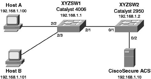
In this scenario, you secure both a CatOS-based switch and an IOS-based switch. By securing each switch, you are not only reducing their vulnerabilities, but also increasing the security of the entire network.

Scenario Exercise

Figure 8-3 illustrates the scenario topology used for Scenarios 8-1, 8-2, and 8-3. Corporation XYZ requires their existing switches to be secured using best practices. They are also about to acquire a larger corporation and need to add new switches to the network. The Corporation XYZ CIO has specified that the current network must be secured, to ensure the new network maintains a tight security policy.

Figure 8-3. Scenarios 8-1, 8-2, and 8-3 Topology


A Catalyst 4006 (XYZSW1) provides access for Hosts A and B. Host A is a dedicated network administration workstation that is used to manage the network. Host B is a user's PC, and should not be allowed management access to any network devices. A Catalyst 2950 (XYZSW2) provides connectivity to the company servers, including a recently installed CiscoSecure asynchronous communications server (ACS). Both switches are interconnected by a single Fast Ethernet trunk.

Scenario Objectives

The scenario objectives are as follows:

  • Configure local user-level authentication (Cisco IOS only)

  • Configure a lockout policy (CatOS only)

  • Configure a login banner

  • Configure session timeouts

  • Configure local authorization (Cisco IOS only)

  • Restrict management access

  • Enable SSH support (CatOS only)

Equipment Needed

The equipment needed is as follows:

  • The workstations and servers in the diagram recommended set up and installed as per the scenario diagram

  • One CatOS and one IOS switch

Command Syntax

This covers the following:

  • Securing a CatOS Switch

  • Securing a Cisco IOS Switch

  • The following sections describe the commands used for each part of the scenario

CatOS Command Syntax

The following new CatOS commands are introduced in this scenario:

  • set authentication

  • set banner motd

  • set logout

  • set ip permit

  • set crypto key rsa

The set authentication Command Syntax

Login authentication is configured using the set authentication login command. You can also control access to privileged configuration mode (enable mode) separately by using the set authentication enable command.

You can individually specify the maximum number of unsuccessful login or enable attempts using the following syntax:

 set authentication {login | enable} attempt maximum_attempts [console | telnet] 

Once the maximum number of attempts is reached, you can define a lockout policy by using the following syntax:

 set authentication {login | enable} lockout time [console | telnet] 

The time parameter is configurable between 30 and 600 seconds, with a value of 0 disabling any lockout; 0 is the default configuration.

NOTE

Unlike a console lockout, which completely blocks console access, a Telnet lockout blocks only the IP address from which the login attempts failed.


The set banner motd Command Syntax

You configure a login banner on CatOS using the set banner motd command, as shown in Example 8-1

Example 8-1. Configuring a Banner on CatOS
 Switch (enable) set banner motd # ********************************** * Unauthorized access prohibited * ********************************** # MOTD banner set 

Notice the use of the # character as a delimiter, which allows you to enter a banner as free text until you terminate the input with the same delimiter. The delimiter can be any character, as long as it does not appear in the desired banner.

The set logout Command Syntax

The set logout command controls how long a session (e.g., a console or Telnet session) can remain idle before being disconnected by the system:

 set logout timeout 

The timeout parameter is specified in minutes and is configurable from 0 (no timeout) to 10000 minutes. The default setting is 20 minutes.

The set ip permit Command Syntax

The set ip permit command restricts management access for Telnet, SSH, and SNMP on CatOS. All restrictions are controlled by the set ip permit command. You must initially specify which hosts are to be permitted management access:

 set ip permit ip-address [mask] [telnet | ssh | snmp | all] 

You can specify network address ranges by configuring the optional mask parameter and you can specify different access policies based upon each management access protocol (e.g., Telnet or SNMP).

Once you have defined your permitted hosts, you then need to enable the permit list:

 set ip permit enable [telnet | ssh | snmp | all] 

You can selectively enable the permit list based upon management protocol, or you can enable all permit lists.

The set crypto key rsa Command Syntax

To enable SSH support, you must create a public/private key pair on the switch using the following syntax:

 set crypto key rsa nbits 

The argument nbits is used to specify the length of the key in bits; valid values are from 512 to 2048. Once this key pair has been created, you are able to connect to the switch using a SSH client.

Cisco IOS Command Syntax

The following new Cisco IOS commands are introduced in this scenario:

  • The username command

  • The login local command

  • The banner command

  • The exec-timeout command

  • The privilege command

  • The access-class command

The username Command and login local Command Syntax

When enabling user-level authentication, the first step is to create user accounts for each user that requires access to the switch. This is achieved by executing the username global configuration command:

 username name password secret 

Next you need to configure each management interface to use local authentication. This is achieved by executing the login local line configuration command, as shown in Example 8-2.

Example 8-2. Enabling Local User-Level Authentication
 Switch(config)# line con 0 Switch(config-line)# login local Switch(config-line)# line vty 0 4 Switch(config-line)# login local 

In Example 8-2, both the console and vty ports are configured to use the local user account database to authenticate users.

The banner Command Syntax

You configure a login banner on Cisco IOS using the banner motd global configuration command, as shown in Example 8-3

Example 8-3. Configuring a Banner on Cisco IOS
 Switch(config)# banner motd # ********************************** * Unauthorized access prohibited * ********************************** # 

Notice the use of the # character as a delimiter, which allows you to enter a banner as free text until you terminate the input with the same delimiter.

It is also possible to display other banners by using one of the arguments to the banner global configuration command listed in Table 8-6.

Table 8-6. Arguments to the banner Global Configuration Command

Argument

Description

exec

Displayed when an exec session is created

incoming

Displayed when a reverse Telnet session is established through a router

login

Displayed after the message of the day (MOTD) but before the username and password prompt


The exec-timeout Command Syntax

The exec-timeout command is used to control how long a session (e.g., a console or telnet session) can remain idle before being disconnected by the switch. The command is applied in line configuration mode as shown in Example 8-4

Example 8-4. Configuring Session Timeouts on Cisco IOS
 Switch(config)# line con 0 Switch(config-line)# exec-timeout 20 30 

The first numeric parameter of the exec-timeout command specifies the number of minutes, while the second numeric parameter specifies the number of seconds. In Example 8-4, the console idle session timeout is set to 20 minutes and 30 seconds.

The privilege Command Syntax

The privilege global configuration mode command is used to define custom, local authorization levels for Cisco IOS commands. You can assign a particular command (or set of commands) to a particular privilege level using the following syntax:

 privilege {configure | exec | interface} level privilege-level command 

You must specify which configuration mode the command exists in (e.g., configure, exec, interface); indicate the desired privilege level; and then specify the command you want to assign. You can replace the level privilege-level portion with the reset keyword to reset the command to its default privilege level.

Once you have assigned the appropriate commands to the privilege level, you must now create an enable password for the new privilege level. This is configured by using the enable password or enable secret (recommended) command:

 enable secret level privilege-level secret 

To access the new privilege level, a user simply appends the desired privilege level when executing the enable command in user mode as shown in Example 8-5

Example 8-5. Accessing a Custom Privilege Level
 Switch> enable 10 Password: ******** Switch# 

By adding the level to the enable command (e.g., enable 10), the desired level is accessed rather than the default enable mode (level 15).

TIP

If you access a higher privilege level, you can use any commands specified in lower privilege levels. When creating privilege levels, it is a good idea to simulate all the commands a user would execute and then add them to the privilege level. Don't forget commands such as configure terminal and exit.


The access-class Command Syntax

The access-class line configuration command is used to apply access lists to management interfaces such as vty ports. To restrict Telnet and SSH access, you first create a simple access list that defines the source addresses of authorized hosts and then apply that access list to the management interface (e.g., line vty 0 4), as shown in Example 8-6. SSH connections are treated as coming in via the virtual terminal (vty) ports and, hence, are configured identically

Example 8-6. Restricting Telnet and SSH Access on Cisco IOS
 Switch(config)# access-list 1 permit 192.168.1.0 0.0.0.255 Switch(config)# line vty 0 4 Switch(config-line)# access-class 1 in 

In Example 8-6, only hosts on the 192.168.1.0/24 subnet are able to access the switch via Telnet or SSH. You must bind the access list that defines the source hosts to the vty ports using the access-class command.

Configuration Tasks

In this scenario, you perform the following tasks:

  • Step 1 Preparing the switches

  • Step 2 Securing the Catalyst OS switch (XYZSW1)

  • Step 3 Securing the Cisco IOS switch (XYZSW2)

Step 1Preparing the Switches

In this step you:

  • Configure the system name and management IP address

  • Interconnect each switch and ensure ping connectivity

  • Provide connectivity for Hosts A, B, and the AAA server

Configuring the System name and Management IP Address

On each switch, ensure you can access the switch via the console port.

Step 1.

On XYZSW1, configure system name, Telnet/enable password of "cisco" and an IP address of 192.168.1.1/24, as shown in Example 8-7.

Example 8-7. Configuring Basic Parameters on XYZSW1
 Console enable Enter password: Console (enable) set system name XYZSW1 System name set. XYZSW1 (enable) set password Enter old password: ***** Enter new password: ***** Retype new password: ***** Password changed. XYZSW1 (enable) set enablepass Enter old password: ***** Enter new password: ***** Retype new password: ***** Password changed. XYZSW1 (enable) set interface sc0 192.168.1.1 255.255.255.0 

Step 2.

On XYZSW2 configure system name, Telnet/enable password of cisco and an IP address of 192.168.1.2/24, as shown in Example 8-8.

Example 8-8. Configuring Basic Parameters on XYZSW2
 Switch> enable Password: Switch# configure terminal Switch(config)# hostname XYZSW2 XYZSW2(config)# enable secret cisco XYZSW2(config)# line vty 0 4 XYZSW2(config-line)# password cisco XYZSW2(config-line)# login XYZSW2(config-line)# interface VLAN1 XYZSW2(config-if)# ip address 192.168.1.2 255.255.255.0 XYZSW2(config-if)# end XYZSW2# copy running-config startup-config Building configuration... [OK] 

Interconnecting the switches

For this scenario you interconnect the switches using crossover unshielded twisted-pair (UTP) cables between Fast Ethernet 802.1Q trunk ports (you can use gigabit Ethernet trunks if you have these). Refer to Figure 8-1 for port assignments.

Step 1.

On XYZSW1, configure 100 Mbps speed and full duplex on port 2/1 and enable trunking using 802.1Q, as shown in Example 8-9.

Example 8-9. Configuring Trunks on XYZSW1
 XYZSW1> (enable) set port speed 2/1 100 Port 2/1 transmission speed set to 100Mbps. XYZSW1> (enable) set port duplex 2/1 full Port 2/1 to full-duplex. XYZSW1> (enable) set trunk 2/1 on dot1q Port(s)  2/1 trunk mode set to on. Port(s)  2/1 trunk type set to dot1q. 

Step 2.

On XYZSW2, configure 100 Mbps speed and full duplex on port 0/1 and enable trunking using 802.1Q, as show in Example 8-10.

Example 8-10. Configuring Trunks on XYZSW2
 XYZSW2# configure terminal XYZSW2(config)# interface fastEthernet0/1 XYZSW2(config-if)# no shutdown XYZSW2(config-if)# speed 100 XYZSW2(config-if)# duplex full XYZSW2(config-if)# switchport mode trunk XYZSW2(config-if)# switchport trunk encapsulation dot1q XYZSW2(config-if)# end XYZSW2# copy running-config startup-config Building configuration... [OK] 

Once these configurations are complete, wait for at least 50 seconds to allow the spanning-tree state of the trunk ports to transition to forwarding.

Step 3.

Verify you are able to ping XYZSW1 from XYZSW2 as shown in Example 8-11.

Example 8-11. Verifying ping Connectivity Between XYZSW1 and XYZSW2
 XYZSW1> (enable) ping 192.168.1.2 !!!!! 

Connecting the Hosts and AAA Server

Ensure all hosts are configured with an IP address, as shown in Figure 8-3. Then, connect each host as shown in Figure 8-3 to the appropriate switch and port.

Step 1.

On XYZSW1, configure 100 Mbps speed, full duplex, and spanning-tree PortFast for ports 2/2 and 2/3 as shown in Example 8-12.

Example 8-12. Configuring Access Ports on XYZSW1
 XYZSW1> (enable) set port speed 2/2-3 100 Ports 2/2-3 transmission speed set to 100Mbps. XYZSW1> (enable) set port duplex 2/2-3 full Port(s)  2/2-3 to full-duplex. XYZSW1> (enable) set spantree portfast 2/2-3 enable Warning: Spantree port fast start should only be enabled on ports connected to a single host.  Connecting hubs, concentrators, switches, bridges, etc. to a fast start port can cause temporary spanning tree loops.  Use with caution. Spantree ports 2/2-3 fast start enabled. 

Step 2.

On XYZSW2, configure 100 Mbps speed and full duplex for port 0/2, as shown in Example 8-13.

Example 8-13. Configuring Access Ports on XYZSW2
 XYZSW2# configure terminal XYZSW2(config)# interface fastEthernet0/2 XYZSW2(config-if)# no shutdown XYZSW2(config-if)# speed 100 XYZSW2(config-if)# duplex full XYZSW2(config-if)# switchport mode access XYZSW2# copy running-config startup-config Building configuration... [OK] 

Step 3.

Ensure that all devices in the network (switches, hosts, servers) can ping each other, as shown in Example 8-14.

Example 8-14. Verifying ping Connectivity Between XYZSW1 and Hosts A, B, and the AAA Server
 XYZSW1> (enable) ping 192.168.1.10 !!!!! XYZSW1> (enable) ping 192.168.1.100 !!!!! XYZSW1> (enable) ping 192.168.1.101 !!!!! 

Step 2Securing the Catalyst OS Switch (XYZSW1)

On XYZSW1, you now perform minor security configurations to enhance the security of Telnet and console access to XYZSW1. In this step you:

  • Set banner, lockout, and session Timeout Parameters

  • Restrict Telnet and SNMP access

  • Enable SSH support

Setting Banner, Lockout, and Session Timeout Parameters

Step 1.

On XYZSW1, configure a banner that is displayed at each login prompt, as shown in Example 8-15.

Example 8-15. Configuring a Banner on XYZSW1
 XYZSW1> (enable) set banner motd # *********************************** *             WARNING             * * Unauthorized access prohibited  * *********************************** # 

Step 2.

On XYZSW1, configure a maximum of three unsuccessful login attempts for Telnet access and five for console access, and set a lockout of 180 seconds for Telnet access and 300 seconds for console access. Also configure a maximum of three unsuccessful enable mode login attempts for all modes of access, with a lockout of 300 seconds, as shown in Example 8-16. You also need to set the idle session timeout to be 5 minutes.

Example 8-16. Configuring Lockout Policy on XYZSW1
 XYZSW1> (enable) set authentication login attempt 3 telnet Login authentication attempts for telnet set to 3. XYZSW1> (enable) set authentication login attempt 5 console Login authentication attempts for console set to 5. XYZSW1> (enable) set authentication login lockout 180 telnet Login lockout time for telnet set to 180. XYZSW1> (enable) set authentication login lockout 300 console Login lockout time for console set to 300. XYZSW1> (enable) set authentication enable attempt 3 Enable mode authentication attempts for console and telnet logins set to 3. XYZSW1> (enable) set authentication enable lockout 300 Enable mode lockout time for console and telnet logins set to 300. XYZSW1> (enable) set logout 5 Sessions will be automatically logged out after 5 minutes of idle time. 

Restricting Telnet Access on XYZSW1

For this scenario, you permit Telnet access only from Host A (192.168.1.100), SNMP access from an SNMP management system at 192.168.1.20, and block Telnet access from all other hosts for both switches.

Step 1.

On XYZSW1, add Host A (192.168.1.100) to the Telnet permit list and add 192.168.1.20 to the SNMP permit list, as shown in Example 8-17.

Example 8-17. Creating Telnet and SNMP Permit Lists on XYZSW1
 XYZSW1> (enable) set ip permit 192.168.1.100 telnet 192.168.1.100 added to Telnet permit list. XYZSW1> (enable) set ip permit 192.168.1.20 snmp 192.168.1.20 added to Snmp permit list. 

Step 2.

On XYZSW1, enable the Telnet and SNMP permit lists, as shown in Example 8-18

Example 8-18. Enabling Telnet and SNMP Permit Lists on XYZSW1
 XYZSW1 (enable) set ip permit enable telnet Telnet permit list enabled. XYZSW1 (enable) set ip permit enable snmp SNMP permit list enabled. 

Step 3.

Verify that you now cannot Telnet to XYZSW1 from Host B. Next verify the permit lists on XYZSW1, as shown in Example 8-19.

Example 8-19. Verifying Telnet and SNMP Permit Lists on XYZSW1
 XYZSW1> (enable) show ip permit    Telnet permit list enabled.    Ssh permit list disabled.    Snmp permit list enabled. Permit List        Mask               Access-Type ----------------   ----------------   ------------- 192.168.1.20                           snmp 192.168.1.100                          telnet Denied IP Address Last Accessed Time Type 192.168.1.101     01/30/02,03:13:44  Telnet 

As you can see, the Telnet and SNMP permit lists are enabled, and the switch has logged the unauthorized Telnet connection attempt from Host B. Example 8-20 shows what a denied host receives when trying to Telnet to XYZSW1.

Example 8-20. Denied Telnet Connection
 C:\>telnet 192.168.1.100 Connecting To 192.168.1.100... Access not permitted.  Closing connection... Connection to host lost. C:\> 

Enabling SSH Support

For this section, you enable SSH support and then disable Telnet access to XYZSW1.

Step 1.

On XYZSW1, generate a 1024-bit RSA public/private key pair as shown in Example 8-21.

Example 8-21. Generating an RSA Key Pair on XYZSW1
 XYZSW1> (enable) set crypto key rsa 1024 Generating RSA keys.... [OK] 

Step 2.

On XYZSW1, configure an IP permit list for SSH access, allowing only Host A (192.168.1.100) to connect via SSH. Then enable the IP permit list (for SSH) as shown in Example 8-22

Example 8-22. Configure an IP Permit List for SSH on XYZSW1
 XYZSW1> (enable) set ip permit 192.168.1.100 ssh 192.168.1.100 added to Ssh permit list. XYZSW1> (enable) set ip permit enable ssh SSH permit list enabled. 

Step 3.

On XYZSW1, verify the creation of the RSA keys, shown below as Example 8-23.

Example 8-23. show crypto key on XYZSW1
 XYZSW1> (enable) show crypto key 

Step 3Securing the Cisco IOS Switch (XYZSW2)

On XYZSW2, you now perform minor security configurations to enhance the security of Telnet and console access to XYZSW2. In this step you:

  • Set banner, lockout, and session timeout parameters

  • Restrict Telnet and SNMP access

  • Configure privilege levels to provide command authorization

Setting Banner, Lockout, and Session Timeout Parameters

Step 1.

On XYZSW2, configure a banner that is displayed at each login prompt, as shown in Example 8-24.

Example 8-24. Configuring a Banner on XYZSW2
 XYZSW2(config)# banner motd # Enter TEXT message.  End with the character '#'. *********************************** *             WARNING             * * Unauthorized access prohibited  * *********************************** # 

Step 2.

On XYZSW2, configure the idle session timeout to be 5 minutes for all management ports, as shown in Example 8-25.

Example 8-25. Configuring Idle Session Timeouts on XYZSW2
 XYZSW2(config)# line vty 0 4 XYZSW2(config-line)# exec-timeout 5 0 XYZSW2(config-line)# line con 0 XYZSW2(config-line)# exec-timeout 5 0 XYZSW2(config-line)# end 

Restricting Telnet Access on XYZSW2

In this section, you permit Telnet access only from Host A (192.168.1.100), SNMP access from an SNMP management system at 192.168.1.20, and block Telnet access from all other hosts.

Step 1.

On XYZSW2, create two simple access lists to allow only the source IP address of Host A and the SNMP manager, as shown in Example 8-26.

Example 8-26. Creating Access Lists on XYZSW2
 XYZSW2(config)# access-list 1 permit host 192.168.1.100 XYZSW2(config)# access-list 2 permit host 192.168.1.20 

Step 2.

On XYZSW2, configure the vty lines (Telnet management interfaces) to restrict management access based on the first access list you created in Step 1, as shown in Example 8-27

Example 8-27. Restricting Telnet Access on XYZSW2
 XYZSW2(config)# line vty 0 4 XYZSW2(config-line)# access-class 1 in 

Step 3.

On XYZSW2, configure the SNMP read-only and read-write community strings to be accepted only from the hosts specified in the second access list you created in Step 1, as shown in Example 8-28.

Example 8-28. Restricting SNMP Access on XYZSW2
 XYZSW2(config)# snmp-server community cisco123 ro 2 XYZSW2(config)# snmp-server community cisco321 rw 2 

Step 4.

Verify that you can connect to XYZSW2 only via Telnet from Host A and cannot connect from Host B (see Example 8-29).

Example 8-29. Failed Telnet to XYWSW2 from Host B
 C:\>telnet 192.168.1.2 Connecting To 192.168.1.2...Could not open a connection to host: Connect failed C:\> 

Configuring Privilege Levels to Provide Command Authorization

For this section, you configure privilege levels that allow network operators to view the system configuration and allow the operator to add a description to an interface.

The following commands are added to a custom privilege level; then a password is assigned to allow operators to gain access to the command set:

  • show running-config (exec mode)

  • configure terminal (exec mode)

  • interface (global configuration mode)

  • description (interface configuration mode)

Step 1.

On XYZSW2, add the appropriate commands to a custom privilege level of 5, as shown in Example 8-30.

Example 8-30. Assigning Commands to a Custom Privilege Leve
 XYZSW2(config)# privilege exec level 5 configure terminal XYZSW2(config)# privilege exec level 5 show running-config XYZSW2(config)# privilege configure level 5 interface XYZSW2(config)# privilege interface level 5 description 

Be sure that you understand the configuration mode (e.g., global configuration or exec) of the commands that you want to add.

Step 2.

On XYZSW2, configure an enable secret password for the custom privilege level, as shown in Example 8-31.

Example 8-31. Configuring an Enable Secret for a Custom Privilege Level
 XYZSW2(config)# enable secret level 5 cisco123 

In Example 8-31, a password of "cisco123" is assigned to privilege level 5.

Step 3.

Test your new privilege level by connecting to the switch via Telnet and logging into the new privilege level. Try all the permitted commands, as well as non-permitted commands (e.g., erase), as shown in Example 8-32.

Example 8-32. Testing Custom Privilege Levels
 User Access Verification Password: ****** XYZSW2> enable 5 Password: XYZSW2# show running-config Building configuration... Current configuration: interface FastEthernet0/1 ... ... XYZSW2# configure terminal XYZSW2(config)# interface fastEthernet0/1 XYZSW2(config-if)# description TESTING XYZSW2(config-if)# end XYZSW2# erase flash         ^ % Invalid input detected at '^' marker. 

In Example 8-32, you access the custom privilege level by using the enable 5 command. Notice that you can execute all the required commands, but when you try to execute an unauthorized command (e.g., erase), IOS notifies you that the command is invalid.


CCNP Self-Study CCNP Practical Studies. Switching
CCNP(R) Practical Studies: Switching (CCNP Self-Study)
ISBN: 1587200600
EAN: 2147483647
Year: 2002
Pages: 135
Authors: Justin Menga

flylib.com © 2008-2017.
If you may any questions please contact us: flylib@qtcs.net