Scenario 5-2: Configuring Layer 3 Switching
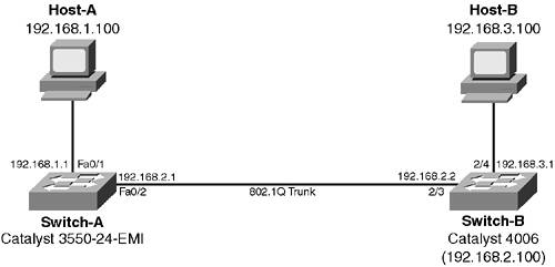
| Layer 3 (L3) switching is a technology that has become very popular in modern campus networks. L3 switching basically refers to a switch that can route. The main difference between a L3 switch and a traditional router is performance. L3 switches are used to route IP traffic at LAN speeds (10/100/1000 Mbps) by utilizing hardware-based wire-speed routing, instead of software-based routing used on Cisco routers. L3 switches can route at speeds seen only in high-end Cisco routers, at a fraction of the cost, the trade-off being that L3 switches can route only between Ethernet media, whereas a Cisco router can route between a variety of LAN and WAN media. In this scenario you configure essentially the same IP topology of Scenario 5-1, but use L3 switches to implement routing instead of Cisco routers. It is very important to ensure you understand exactly how a L3 switch operates because these devices are becoming less expensive and are becoming more common in the marketplace. Figure 5-12 shows the topology used for this scenario. The topology might not look like too much in terms of routing; however, each switch possesses both switched and routed interfaces that allow the switch to act as a L3 switch. In this lab, you enable connectivity between Host-A and Host-B, using the IP addressing and topology shown in Figure 5-12. Figure 5-12. Scenario 5-2 Topology
The following describes the function of each component of the lab topology shown in Figure 5-12:
Understanding the Catalyst 3550 Series Multilayer SwitchesThe Catalyst 3550 series is the next-generation switching family from Cisco for small to medium enterprises. The Catalyst 3550 switches are Layer 3/4 aware (can classify packets based upon Layer 3/4 information) and are also capable of performing Layer 3 routing. The Catalyst 3550 series switches consist of the following switches:
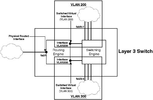
The Catalyst 3550-24 and 3550-48 switches are available with a Layer 2only IOS image (known as SMI) or with a Layer 3switching IOS image (known as EMI). The SMI version can be upgraded to the EMI version if required, which provides a low cost migration path for converting a Layer 2 switching architecture to a Layer 3 switching architecture. Both the Catalyst 3550-12T and 3500-12G are Layer 3 switches that run an EMI image and cannot be purchased as just a Layer 2 switch. The new Cisco IOS-based L3 switches from Cisco are much more integrated than older L3 switch implementations because of the use of the same management interface (Cisco IOS only) for both Layer 2 and Layer 3 functionality, rather than the use of both CatOS (for Layer 2 functionality) and Cisco IOS (for Layer 3 functionality). To understand exactly how L3 switching works on the Catalyst 3550, it is often easier to draw out the L2 switch and L3 router components separately on a piece of paper. Figure 5-13 demonstrates separating out each of the L3 switch components used in Switch-A. Figure 5-13. Layer 3 Switch (Switch-A) Logical Components
In Figure 5-13, you can see the concept of a L3 switch is essentially the same as a traditional separated L2 switch and L3 router topology. Within the L3 switch, a dedicated routing engine acts exactly like a normal router. The only real difference between a traditional L3 switch and router is that a L3 switch performs the L3 routing function in hardware, at much higher speeds than a software-based L3 router, and the internal connection between the routing engine and switching engine is not a bottleneck the way an external connection is. Notice in Figure 5-13 the two types of routed interfaces on a L3 switch:
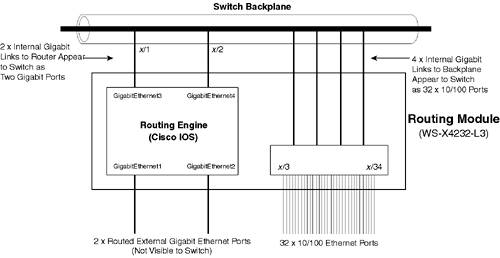
The physical interface is simply a port on the switch that acts exactly like an Ethernet port on a router. You can configure any port on the switch as a routed interface, making L3 switching much easier to understand and configure. The routed interface feature is available on all Catalyst 3550 L3 switches, as well as the Catalyst 4000/4500 with Supervisor 3/4 and the Cisco IOS-based Catalyst 6000/6500 with the Multilayer Switch Feature Card (MSFC) operating in native IOS mode. NOTE On the switches listed above, a physical interface can be configured as a traditional switch (Layer 2) port or a routed interface. On older L3 switching modules, such as the Catalyst 4000 routing module, Catalyst 5000 RSM, and Catalyst 6000/6500 with MSFC running hybrid mode, you cannot configure a switched port on the switch as a routed interfaceyou can only use SVI routed interfaces, as the routing component has no control over any switched interfaces. The SVI is an internal virtual interface that attaches to a particular VLAN on the switch. The SVI is essentially an internal routed interface attached to the L3 engine belonging to a particular VLAN. This allows other devices attached to switched physical ports within the VLAN to communicate at a Layer 3 level with the routing engine of the L3 switch. In Figure 5-13, two SVI interfaces are displayedone for VLAN 200 and one for VLAN 300. Creating an SVI interface is simple; you simply create the SVI by using the IOS interface VLAN x global configuration mode command, where x is the VLAN ID to which you want to attach the SVI to. In Figure 5-13, the SVI for VLAN 200 is configured using the interface VLAN 200 command, while the SVI for VLAN 300 is configured using the interface VLAN 300 command. Once you have created the SVI, you configure it with normal L3 parameters (such as IP addressing) just as you would for a physical routed interface. NOTE If you are familiar with configuring integrated routing and bridging (IRB) on Cisco routers, an SVI is similar in concept to a bridge virtual interface (BVI), and VLANs on Catalyst switches are similar to bridge groups on Cisco routers. Understanding the Catalyst 4000 Router Module (WS-X4232-L3)This lab includes configuration of the Catalyst 4000 router module, which is the module used to turn the Catalyst 4000 with a Supervisor 1 or 2 module into a L3 switch. NOTE The Catalyst 4000 has newer Supervisor 3 or Supervisor 4 modules available, which are Cisco IOS-based with integrated L3 switching functionality (similar to the Catalyst 3550). You cannot use the WS-X4232-L3 router module in Catalyst 4000 switches with the Supervisor 3/4 module installed. The router module is very popular with a large installation base worldwide and it is important that you understand the architecture of the router module before installing and configuring it. The router module is essentially a standalone router that is powered by the Catalyst 4000 chassis and has gigabit interfaces that attach to the Catalyst 4000 backplane. The router module has its own processor, memory, flash, operating system (Cisco IOS), and management interface. All routing configuration is configured using the router module Cisco IOS interface. No routing configuration is provided by the CatOS management interface of the Catalyst 4000 switch. Figure 5-14 shows the internal architecture of the Catalyst 4000 router module. Figure 5-14. Catalyst 4000 Router Module Architecture
In the Catalyst 4000 architecture, each module is provided with six internal gigabit links to the switch backplane. In Figure 5-14, you can see that two of these are attached to the Cisco IOS routing engine on the routing module, while the remaining internal gigabit links are attached to the 32-port 10/100 Ethernet card. The Catalyst 4000 Supervisor 1/2 sees the two gigabit links to the routing engine as ports x/1 and x/2, where x is the slot in which the routing module is installed (e.g., 2/1 and 2/2 if the routing module is installed in slot 2). The two external Gigabit Ethernet ports located on the routing module are directly attached routed interfaces on the routing engine and are not visible to the Supervisor engine. The 32-port 10/100 card is attached directly to the switching engine and has no relationship with the routing engine except that they both share the same physical chassis. The numbering of the ports starts from x/3 (port 1) and finishes at x/34 (port 32). To allow Catalyst 4000 ports to communicate with the routing engine, the two internal gigabit links are normally configured as an EtherChannel bundle, which operates as an 802.1Q trunk. This means the throughput of the routing engine is limited to up to 2 Gbps full-duplex, and the routing engine can attach to any VLAN on the switch by use of the trunk. To attach the routing engine to a particular VLAN on the switch, an SVI must be created for the VLAN. This enables the routing engine to communicate on the VLAN at a Layer 3 level. NOTE The Catalyst 4000 L3 routing module can route IP packets at 6 million packets per second, although the actual performance achieved is limited to 2 Gbps based upon the backplane connection to the Catalyst 4000 switch engine. Understanding the Inter-VLAN Routing Packet FlowNow that you understand the architectures of both the Catalyst 3550 L3 switch and the Catalyst 4000 routing module, it is important that you understand how packets are routed between Host-A and Host-B in this scenario. Figure 5-15 shows the topology of Figure 5-12 from an inter-VLAN routing and packet flow perspective. Figure 5-15. Scenario 5-2 Inter-VLAN Routing Topology
NOTE In this scenario, you configure a routed physical interface on Switch-A (fa0/1), with all remaining routed interfaces being SVI interfaces. In Figure 5-15 notice the architectural differences between Switch-A and Switch-B. The Catalyst 4006 with router module is essentially a high-speed router-on-a-stick implementation, much like the relationship between Switch-A and Router-B in Scenario 5-1; however, the routing engine in the router module is much faster than a 2600 series router or similar (the router module is based upon the 7200 series platform). The fact that the Catalyst 4006 and router module are operating in a router-on-a-stick configuration is further indicated by the fact that each has a separate management interface. The Catalyst 3550 switch and other Cisco IOS L3 switches have an integrated management interface for both routing and switching. |

EAN: 2147483647
Pages: 135
- Chapter IV How Consumers Think About Interactive Aspects of Web Advertising
- Chapter VI Web Site Quality and Usability in E-Commerce
- Chapter X Converting Browsers to Buyers: Key Considerations in Designing Business-to-Consumer Web Sites
- Chapter XV Customer Trust in Online Commerce
- Chapter XVII Internet Markets and E-Loyalty