Scenario Prerequisites
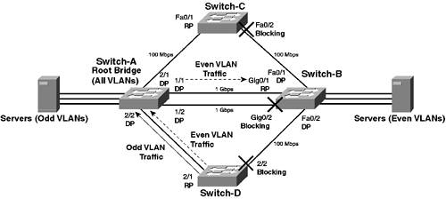
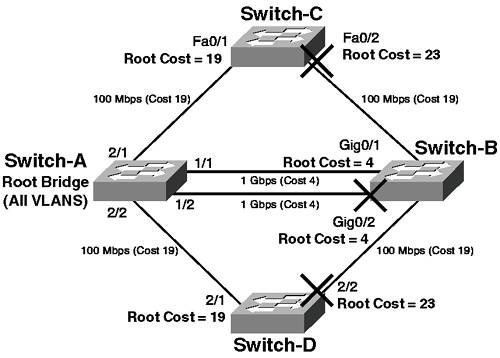
| Although this scenario continues on from the Scenario 4-1, to successfully commence the configuration tasks required to complete this scenario, you must first create each of the new VLANs that are needed to allow STP load sharing. Example 4-16 through Example 4-19 show the VLAN configuration required on each switch. Example 4-16. Scenario 4-2 Prerequisite Configuration for Switch-ASwitch-A> (enable) set vlan 2 name VLAN02 VTP advertisements transmitting temporarily stopped, and will resume after the command finishes. Vlan 2 configuration successful Switch-A> (enable) set vlan 3 name VLAN03 VTP advertisements transmitting temporarily stopped, and will resume after the command finishes. Vlan 3 configuration successful Switch-A> (enable) set vlan 4 name VLAN04 VTP advertisements transmitting temporarily stopped, and will resume after the command finishes. Vlan 4 configuration successful Example 4-17. Scenario 4-2 Prerequisite Configuration for Switch-BSwitch-B# configure terminal Switch-B(config)# vlan 2 Switch-B(config-vlan)# name VLAN02 Switch-B(config-vlan)# exit Switch-B(config)# vlan 3 Switch-B(config-vlan)# name VLAN03 Switch-B(config-vlan)# exit Switch-B(config)# vlan 4 Switch-B(config-vlan)# name VLAN04 Switch-B(config-vlan)# exit Example 4-18. Scenario 4-2 Prerequisite Configuration for Switch-CSwitch-C# configure terminal Switch-C(config)# vlan 2 Switch-C(config-vlan)# name VLAN02 Switch-C(config-vlan)# exit Switch-C(config)# vlan 3 Switch-C(config-vlan)# name VLAN03 Switch-C(config-vlan)# exit Switch-C(config)# vlan 4 Switch-C(config-vlan)# name VLAN04 Switch-C(config-vlan)# exit Example 4-19. Scenario 4-2 Prerequisite Configuration for Switch-DSwitch-D> (enable) set vlan 2 name VLAN02 VTP advertisements transmitting temporarily stopped, and will resume after the command finishes. Vlan 2 configuration successful Switch-D> (enable) set vlan 3 name VLAN03 VTP advertisements transmitting temporarily stopped, and will resume after the command finishes. Vlan 3 configuration successful Switch-D> (enable) set vlan 4 name VLAN04 VTP advertisements transmitting temporarily stopped, and will resume after the command finishes. Vlan 4 configuration successful Root Bridge PlacementAn important concept to understand with regards to STP load sharing is that a unique spanning-tree instance (including root bridge, topology, timers, etc.) exists per VLAN, which means you can have different spanning-tree topologies per VLAN. In this scenario, four VLANs exist: VLANs 1 and 3 (with servers attached to Switch-A) and VLANs 2 and 4 (with servers attached to Switch-B). The major traffic distributions for each VLAN clearly take place via each respective switch. Figure 4-12 shows the network with Switch-A acting as the root bridge for all VLANs. Figure 4-12. Spanning Tree Topology with Switch-A as Root for All VLANs
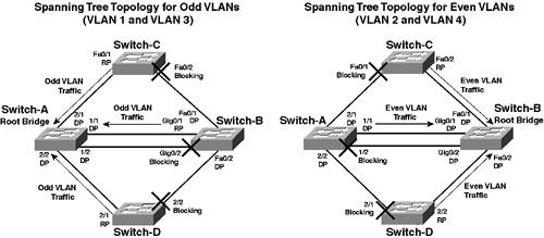
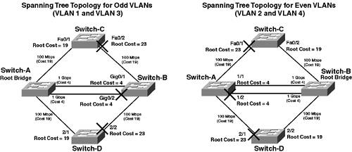
In this example, the root bridge is the same for all VLANs, and by default, the topology generated throughout the rest of the network is identical for each VLAN. Look at Switch-D (the same topology is used for all VLANs); only the uplink to Switch-A is active, with the uplink to Switch-B idle. This configuration means that the uplink to Switch-A is susceptible to oversubscription. The path for traffic in odd VLANs is also not ideal, because client/server traffic must traverse Switch-A to reach servers attached to Switch-B. A simple technique to alter the spanning-tree topology for different VLANs is to change the root bridge for each VLAN. Figure 4-13 shows the network with Switch-A acting as the root bridge for odd VLANs (VLAN 1 and VLAN 3), and Switch-B acting as the root bridge for even VLANs (VLAN 2 and VLAN 4). Figure 4-13. Spanning Tree Topology with Switch-A as Root for Odd VLANs and Switch-B as Root for Even VLANs
Switch-C and Switch-D now send odd VLAN traffic directly to Switch-A and even VLAN traffic directly to Switch-B. This topology is clearly more efficient than that shown in Figure 4-12, minimizing the number of switch hops and spreading the traffic load over the available uplinks. Notice, however, that the same link is used between Switch-A and Switch-B. This feature is the discussion of the next section. Port PriorityRecall that spanning tree uses a simple algorithm (STA) to determine the spanning-tree topology, which involves the comparison of BPDUs as follows:
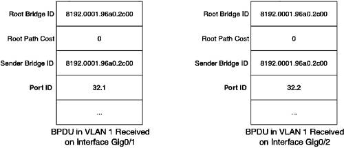
If you look at Figure 4-13, you may notice that for both VLAN topologies, the active link between Switch-A and Switch-B is the same link. A more efficient topology would be to have one link active for odd VLANs and the other active for even VLANs. Why does this not occur, even though the root bridges for each VLAN are different? To find the answer, you need to examine the spanning-tree topology calculation. First, consider VLAN 1 (an odd VLAN); because Switch-A is the root bridge, all ports on Switch-A are put into the forwarding state. Thus, the actual switch that determines which link is active is Switch-B. When the interfaces attached to Switch-A transition from a Shutdown state into a Listening state, Switch-B receives BPDUs from Switch-A on both links. Switch-B must choose a root port (the port on the switch that is closest to the root) and has received two candidate BPDUs. Figure 4-14 illustrates each of these BPDUs (assume the bridge ID of Switch-A is 8192.0001.96a0.2c00). Figure 4-14. BPDUs (VLAN 1) Received on Switch-B Interfaces Gig0/1 and Gig0/2
Because Switch-A is the root bridge it uses the following values for each field:
You can see that the BPDUs received are almost identical and that the only differentiator between the two is the port ID. The port ID is a 16-bit structure that includes a port priority value (default of 32 on CatOS, default of 128 on Cisco IOS) and a unique identifier that identifies the egress port that the BPDU was sent from. Figure 4-15 shows the port ID field structure. Figure 4-15. Port ID Structure
Notice that CatOS uses only 6 bits for the port priority value (allowing for a configurable range of 0 Referring back to Figure 4-14, you can see that the port ID received on interface Gig0/1 has a value of 32.1the first portion (32) indicates a port priority of 32 and the second portion (1) indicates the egress port identifier on Switch-A. Because the BPDU received on interface Gig0/1 has the lower port ID (32.1) compared to that received on interface Gig0/2 (32.2), interface Gig0/1 is chosen as the root port and put into a Forwarding state. The next step for Switch-B in the Listening phase is to decide if interface Gig0/2 should be Forwarding or Blocking (choosing the designated port for the segment). Switch-B is receiving the BPDU shown in Figure 4-15 on interface Gig0/2 and compares this BPDU with the BPDU Switch-B sends out interface Gig0/2. Figure 4-16 compares the BPDU that Switch-B sends out interface Gig0/2, and the BPDU received from Switch-A on interface Gig0/2 of Switch-B (assume the bridge ID of Switch-B is 28673.0009.b7aa.9c80). Figure 4-16. BPDUs (VLAN 1) Sent and Received by Switch-B on Interface Gig0/2
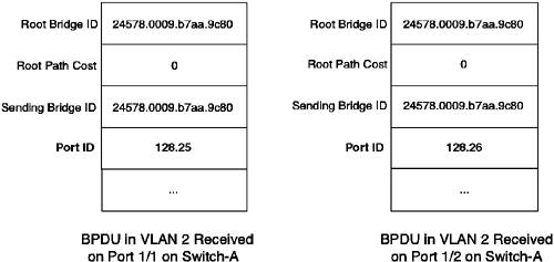
Switch-B decides if interface Gig0/2 is designated (Forwarding) for the segment attached by running the spanning-tree algorithm. Because the root bridge ID fields are the same, the next decision sequence is tested. This compares root path costs, with the lower root path cost winning. Switch-B sees that a switch (in this case the root bridge or Switch-A) has a lower cost (0 as compared to 19) to reach the root bridge, and hence, blocks interface Gig0/2, preventing a loop in the network. Now, examine the same process for VLAN 2 (an even VLAN). In this case, Switch-B is the root bridge, and hence, all ports on Switch-B are put into the Forwarding state. Switch-A needs to choose a root port and performs the same procedures as discussed for Switch-B in VLAN 1. Figure 4-17 shows the BPDUs that are compared when deciding the root port on Switch-A (assume the bridge ID of Switch-B in VLAN 2 is 24578.0009.b7aa.9c80). Figure 4-17. BPDUs (VLAN 2) Received on Switch-A Port 1/1 and Port 1/2
NOTE The priority of Switch-B is 24578 because Switch-B has been configured using the root macro. This process assigns a switch priority of 24578, which is then added to the extended system ID for VLAN 2 (2), giving a bridge priority value of 24578. Notice that the port IDs received include a priority of 128, because Switch-B is a Cisco IOS-based switch. You should be able to quickly see that port 1/1 on Switch-A is chosen as the root port because the port ID of the configuration BPDU received on port 1/1 is lower than that the port ID of the configuration BPDU received on port1/2. Following the same logic for Switch-B in choosing the designated port on the segment attached to port 1/2, port 1/2 on Switch-A is placed into the Disabled state. So far, the fact that the same link is used for traffic on both VLANs has been proved. The goal is to now change this behavior so that a different link is used per VLAN. The parameter that needs to vary is the selection of the root port on the non-root bridge. For example, if Switch-B chose port 1/1 as the root port for VLAN 1, and Switch-A chose port 1/2 as the root port for VLAN 2, the load sharing goal would be achieved. Now remember that the deciding factor in selecting the root port was the port ID, due to all of the other fields being identical. In each case, the port ID of configuration BPDUs received on port 1/1 on each switch was lower, hence, causing this port to be chosen as the root port for both VLANs. If you could alter the port ID for port 1/2 of the root bridge on one of the VLANs, then port 1/2 on the opposite switch would be chosen as the root port, and both links would be active for each different VLAN. The port ID field is a 16-bit field made up of a 6-bit priority subfield and a 10-bit port number subfield. The administratively configurable priority subfield is in the high-order bits of the port ID and, hence, directly controls the port ID value. The priority range is 0 to 255, and the lowest priority value is always considered the preferred value. By default, the port priority is 32 on CatOS-based switches and 128 on Cisco IOS-based switches. You can modify port priority for an entire physical port (all VLAN STP instances inherit the physical port priority), or you can modify the port priority on a per VLAN basis for each port. Figure 4-18 shows the BPDUs received by Switch-A if you lower the port ID for VLAN 2 on Switch-B to 127. Figure 4-18. BPDUs (VLAN 2) Received on Switch-A Port 1/1 and Port 1/2 after Port Priority Has Been Altered on Switch-B
With the BPDUs received in Figure 4-18, when Switch-A is selecting its root port, it now selects port 1/2 as the root port because the port ID of the BPDU received on port 1/2 from Switch-B (127.26) is lower than the port ID received on port 1/1 (128.25). Notice how you needed to change the port ID on the opposing switch (Switch-B) and not the actual switch (Switch-A) that was making the decision. This concept of configuring the opposite switch from the switch that is actually making the decision is counterintuitive and can lead to some confusion. Another limitation of altering port priority is where it has bearing on the selection of the spanning-tree topology. Because the port ID is used as the final selection criteria, it has effect only when you have multiple links to the same remote switch. The STA defines that the sender bridge ID is compared before port ID. If your switch has multiple links to different switches, then received sender bridge IDs are different and are used to select the active path before processing of the port ID is possible. If you have multiple links to the same switch, you receive the same sending bridge ID over each link, leaving the path selection to the port ID. The fact that the port ID is the last selection criteria used if all other criteria are equal is the biggest limiting factor for choosing to manipulate port ID to modify the spanning-tree topology. Port CostFigure 4-13 showed a method of achieving load sharing by ensuring the root bridge for each VLAN was different. This method is actually a crude form of altering root path costs to ensure that a load sharing topology is chosen. Figure 4-19 shows Figure 4-13 with the root path costs for each link on every non-root switch. If you look at the costs on Switch-C and Switch-D for each STP topology, you can see that changing the root bridge for each VLAN has the effect of altering the root path cost so that a different uplink is used for each VLAN. Figure 4-19. Topology of Figure 4-13 with Root Path Costs
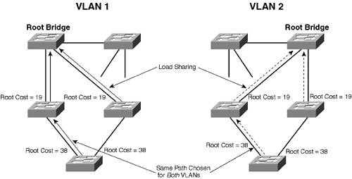
In more complex environments, changing the root bridge for a VLAN might not introduce the desired load sharing topology. Figure 4-20 shows a more complex LAN topology that supports multiple VLANs (VLAN 1 and VLAN 2), with a separate root bridge being configured for each VLAN: Figure 4-20. Complex LAN Topology with Different Root Bridge Configurations for VLAN 1 and 2
NOTE The topology described in Figure 4-20 is for demonstration purposes and is not a recommended design. In modern networks, it is best to limit the reach of spanning tree, instead using a multilayer topology that benefits from the fast convergence and inherent load sharing capabilities of Layer 3 routing protocols. In Figure 4-20, only the active paths in the STP topology for each VLAN are displayed. All switches are interconnected by 100-Mbps connections, which means each link has a default cost of 19. You can see that having the root bridge for each VLAN on a different core switch achieves a load sharing topology for the links that are directly attached to the root bridge (i.e., between the core and distribution switches). However, consider the links between the access switch and distribution switches. Because both distribution switches advertise the same root path cost (19) for both VLANs, the access switch bases its forwarding path decision on the lowest sending bridge ID because the root path cost (38) is the same via either switch (assume in this example that the left-hand distribution switch has the lower bridge ID). Thus, for both VLAN spanning-tree topologies, the access switch chooses the same forwarding path. For this topology, changing the root bridge for each VLAN does not have the desired load sharing effect throughout the entire network. A much more effective method of configuring spanning tree load sharing is to use VLAN port cost to control selection of active links. NOTE You can modify port cost for an entire physical port (all VLAN STP instances that do no have an explicating configured VLAN port cost inherit the physical port cost), or you can modify the port cost on a per VLAN basis for each port (also known as the VLAN port cost). For example, assume that for this scenario, you are restricted by the fact that Switch-A must be the root bridge for all VLANs. Without modifying VLAN port costs, the same spanning tree topology is now chosen for all VLANs. Figure 4-21 shows the topology for all VLANs using the default port costs. Figure 4-21. Scenario Topology with Default Port Costs
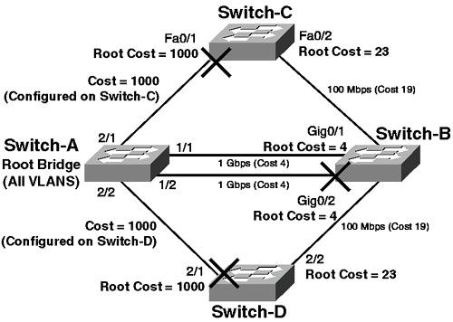
Switch-C forwards all traffic via port Fa0/1 because this port represents the lowest cost path (19) to the root bridge. Similarly Switch-D forwards all traffic via port 2/1. Figure 4-22 shows the topology in Figure 4-21 with manually configured port costs for the interface Fa0/1 on Switch-C and port 2/1 on Switch-D. Figure 4-22. Scenario Topology with Manually Configured Port Costs
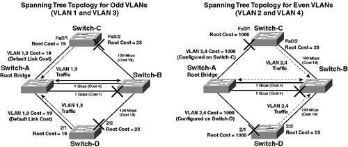
In Figure 4-22, the port cost of Switch-C interface Fa0/1 has been manually configured as 1000, giving a root path cost of 1000 via this interface. Because Switch-C can reach the root bridge via Switch-B with a cost of 23 (19 for the Switch-A NOTE It is important to understand that each switch receiving a configuration BPDU adds the root path cost advertised in the BPDU to the cost of the port that the BPDU was received upon. When a switch sends a configuration BPDU, it does not add the cost of the link of the port that the BPDU is being sent out; instead, this function is left to the receiving switch. Cisco switches enable you to configure port cost on a per VLAN basis, so you can apply the configuration used in Figure 4-23 for a specific VLAN, controlling the traffic path for that particular VLAN. Figure 4-23 shows the scenario topology with manually configured port costs for each VLAN. Figure 4-23. Scenario Topology with Manually Configured VLAN Port Costs
For Switch-C, the port cost on port Fa0/1 for VLAN 2 and VLAN 4 has been configured as 1000, forcing port Fa0/2 to be the active path toward the root bridge for these VLANs. On Switch-D, the port cost on port 2/1 for VLAN 2 and VLAN 4 has also been configured as 1000 to achieve the same result. Configuring STP Load SharingTo configure the requirements for the topology in Figure 4-11, you need to perform the following tasks:
NOTE Before beginning configuration, if you are using the same topology used for Scenario 4-1, you should remove the custom spanning tree configuration of that scenario and then configure Switch-A as the root bridge for all VLANs. Configuring STP Load Sharing on Switch-CAs discussed in this scenario, the recommended method of configuring STP load sharing is to modify the STP cost parameter for logical ports in each STP instance. Referring to Table 4-2, the default costs for the 100-Mbps links on Switch-C are 19, which means that for all VLANs, Switch-C has a root path cost of 19 via Switch-A (the root bridge) and of 23 via Switch-B. So, by default, Switch-C forwards all traffic for all VLANS over the uplink to Switch-A, because Switch-A is the root bridge for both VLANs, leaving the uplink to Switch-B idle. To configure Switch-C so that traffic for even VLANs (VLAN 2 and VLAN 4) is forwarded out interface Fa0/2 to Switch-B instead of out interface Fa0/1, you must configure an STP cost greater than 23 (the cost via Switch-B to the root bridge) on the logical port associated with VLAN 1 on interface Fa0/1. To modify STP costs on Cisco IOS for a logical port, you use the spanning-tree vlan interface configuration command, which has the following syntax: spanning-tree vlan vlan-id cost cost NOTE You can configure the cost of a physical interface using the spanning-tree cost cost interface configuration command. Each logical port associated with the physical interface inherits this cost, unless the cost for the logical interface is explicitly configured. Example 4-20 demonstrates the configuration required on Switch-C to force Switch-C to use the uplink to Switch-B as the forwarding path for VLAN 2 traffic. Example 4-20. Configuring STP Load SharingSwitch-C# configure terminal Switch-C(config)# interface fa0/1 Switch-C(config-if)# spanning-tree vlan 2 cost 1000 Switch-C(config-if)# spanning-tree vlan 4 cost 1000 By configuring the logical ports in VLAN 2 and VLAN 4 with a cost of 1000, Switch-C calculates that for even VLANs, the cost to the root bridge is 1000 (1000 for fa0/1 on Switch-C + 0 for the root bridge Switch-A) via the uplink to Switch-A, and that the cost via the uplink to Switch-B is 23 (19 for Fa0/2 on Switch-C + 4 for Gig0/1 on Switch-B). Therefore, Switch-C always chooses interface Fa0/2 as its root port for even VLANs, and interface Fa0/1 becomes a blocked port as Switch-A becomes the designated bridge (because it is the root bridge) for the segment between Switch-A and Switch-C. Although STP load sharing is now configured (VLAN 1 and VLAN 3 do not require configuration because traffic for these VLANs is already being forwarded over the correct uplink), it is good practice to ensure that odd VLAN traffic is forwarded out the uplink to Switch-A, by configuring a high cost for the logical port in the odd VLANs on the uplink to Switch-B (Fa0/2). Example 4-21 demonstrates this configuration. Example 4-21. Configuring STP Load SharingSwitch-C# configure terminal Switch-C(config)# interface fa0/2 Switch-C(config-if)# spanning-tree vlan 1 cost 1000 Switch-C(config-if)# spanning-tree vlan 3 cost 1000 The root path cost for VLAN 1 and VLAN 3 via Switch-B has now increased to 1004, while the root path cost via Switch-A is 19. This configuration means it is very unlikely Switch-C will forward traffic for odd VLANs out interface Fa0/2, unless, of course, Switch-A fails. Configuring STP Load Sharing on Switch-DOn Switch-D (CatOS), you need to perform the same tasks you performed on Switch-C. To configure the cost of an STP logical port within a VLAN on CatOS, you use the set spantree portvlancost command: set spantree portvlancost mod/port cost cost [vlan_list] The vlan_list parameter allows you to specify the VLANs (logical ports) that the cost will be applied to. NOTE You can configure the cost of a physical port using the set spantree portcost mod/port cost cost command. Each logical port associated with the physical port inherits this cost, unless the cost for the logical port is explicitly configured. On CatOS, you can configure only a single portvlancost value per physical port. What this means is that if, for example, you configure a portvlancost of 1000 for VLAN 1 on port 2/1, you cannot also configure a separate portvlancost of 2000 for VLAN 2 on the same port. If you did this, the portvlancost for VLAN 1 would change to the second value you configured (2000). This limitation is implemented to reduce configuration file size, saving NVRAM usage. NOTE This limitation should not cause too many issues because you are merely using cost to influence whether or not a port forwards traffic. Because this decision has two possible outcomes for a logical port (forward or block), you need only two values to differentiate the two outcomes. For VLANs that you wish the port to forward traffic on, do not configure the portvlancost parameter; instead, allow the logical port to inherit a low (or the default) physical port (portcost) cost. For VLANs that you do not wish the port to forward traffic for, configure a high (portvlancost) cost and ensure each of the VLANs are assigned this cost. Example 4-22 demonstrates the configuration required on Switch-D. Example 4-22. Configuring STP Load Sharing on Switch-DSwitch-D> (enable) set spantree portvlancost 2/1 cost 1000 2,4 Port 2/1 VLANs 1,3,5-1005,1025-4094 have path cost 19. Port 2/1 VLANs 2,4 have path cost 1000. This parameter applies to trunking ports only. Switch-D> (enable) set spantree portvlancost 2/2 cost 1000 1,3 Port 2/2 VLANs 2,4-1005,1025-4094 have path cost 19. Port 2/2 VLANs 1,3 have path cost 1000. This parameter applies to trunking ports only. In Example 4-22 the first command ensures traffic for VLANs 2 and 4 is forwarded out port 2/2 over the uplink to Switch-C. The second command ensures traffic for VLANs 1 and 3 is forwarded out port 2/1 over the uplink to Switch-A, although this behavior is already implemented due to Switch-A being the root bridge. Example 4-23 shows what happens when you configure the portvlancost for VLAN 6 as 2000 on port 2/1. Example 4-23. Modifying STP porvlancost on Switch-D Switch-D> (enable) set spantree portvlancost 2/1 cost 2000 6 Port 2/1 VLANs 1,3,5,7-1005,1025-4094 have path cost 19. Port 2/1 VLANs 2,4,6 have path cost 2000. This parameter applies to trunking ports only. Notice that the portvlancost parameter for VLANs 2 and 4 is also modified when you configure the portvlancost parameter for VLAN 6. This change is due to the limitation of portvlancost on CatOS discussed earlier. Configuring STP Load Sharing Between Switch-A and Switch-BAt this stage you have configured STP load sharing so that Switch-C and Switch-D load share odd and even VLAN traffic over separate links. With the configuration so far, all VLAN traffic is sent over the same link between Switch-A and Switch-B, which is not the most ideal use of the dual links configured between the two switches. As discussed earlier in this scenario, you can use port priority to implement load sharing across two links that are connected between the same switches. On a CatOS switch, the default priority of every port is 32, with a configurable range of 0-63. You cannot modify the port index that uniquely represents each port, so you must lower the port priority to make the port ID more preferred. To modify the port priority for a particular VLAN, use the following command: set spantree portvlanpri mod/port priority priority [vlan_list] The priority configured must be a multiple of 16. If you specify a value that is not a multiple of 16, the port priority is converted to the nearest multiple. The vlan_list parameter allows you to specify the VLANs (logical ports) to which the port priority is applied. NOTE You can configure the priority of a physical port using the set spantree portpri mod/port priority cost command. Each logical port associated with the physical port inherits this cost, unless the cost for the logical port is explicitly configured. Because Switch-B is the switch that decides which of the links to Switch-A should be forwarding based upon BPDUs received from Switch-A, you need to configure the VLAN port IDs on Switch-A to influence the active link selected for each VLAN. Example 4-24 demonstrates the configuration required on Switch-D. Example 4-24. Configuring STP Load Sharing on Switch-ASwitch-A> (enable) set spantree portvlanpri 1/1 priority 16 1,3 Port 1/1 VLANs 2,4-1005,1025-4094 using portpri 32. Port 1/1 VLANs 1,3 using portpri 16. Switch-D> (enable) set spantree portvlanpri 1/2 priority 16 2,4 Port 1/2 VLANs 1,3,5-1005,1025-4094 using portpri 32. Port 1/2 VLANs 2,4 using portpri 16. In Example 4-24, the first command ensures that Switch-B places the port attached to port 1/1 on Switch-A into a Forwarding state for VLANs 1 and 3. The second command ensures that Switch-B places the port attached to port 1/2 on Switch-A into a Forwarding state for VLANs 2 and 4, allowing for load sharing of traffic. Take note that the configuration of Example 4-24 is certainly not the recommended or best configuration for the topology between Switch-A and Switch-B. The best solution is to configure an EtherChannel bundle that is designed to automatically accommodate load sharing and redundancy at the physical layer, rather than at Layer 2, and that simplifies the spanning-tree topology. An EtherChannel bundle appears as a single Layer 2 connection to STP, and any link failure within the bundle is handled within seconds, in a fashion that is transparent to STP, improving stability (i.e., STP does not even know a failure has occurred because the Layer 2 protocol of the bundle remains up during the failure). The load sharing properties of EtherChannel are also much more granular than spanning tree, allowing traffic within a single VLAN to be load shared based upon parameters such as source/destination MAC address or IP address. STP does not provide load sharing to this detail; its load sharing can be implemented only on a per VLAN basis. Example 4-25 demonstrates the configuration required on Switch-A to configure the links to Switch-B as an EtherChannel bundle. Example 4-25. Configuring an EtherChannel Bundle on Switch-ASwitch-A> (enable) clear spantree portvlanpri 1/1 1,3 Port 1/1 vlans 1-1005, 1025-4094 using portpri 32 Switch-A> (enable) clear spantree portvlanpri 1/2 2,4 Port 1/2 vlans 1-1005, 1025-4094 using portpri 32 Switch-A> (enable) set port channel 1/1-2 mode desirable Port(s) 1/1-2 are assigned to admin group 51. Port(s) 1/1-2 channel mode set to desirable. In Example 4-25, you first clear the spanning-tree configuration of Example 4-24 by resetting the port VLAN priority configuration of ports 1/1 and 1/2 to the default value of 32, because an EtherChannel bundle will not form if the spanning-tree parameters are not identical for all ports in the bundle. TIP Always set the PAgP mode to desirable for spanning-tree links. Using the on mode removes the monitoring capabilities of PAgP. On older Cisco IOS Catalyst switches, such as the 2900XL and 3500XL series, the switches do not support PAgP, so you must force ports on the remote switch connected to these older switches to form an EtherChannel bundle. Example 4-26 demonstrates the configuration required on Switch-B to configure the links to Switch-A as an EtherChannel bundle. Example 4-26. Configuring an EtherChannel Bundle on Switch-BSwitch-B# configure terminal Switch-B(config)# interface range gig0/1 2 Switch-B(config-if-range)# channel-group 1 mode desirable Creating a port-channel interface Port-channel1 At this stage, the EtherChannel bundle should form (assuming all ports and interfaces are configured identically). Example 4-27 verifies that the EtherChannel bundle has formed. Example 4-27. Verifying an EtherChannel Bundle on Switch-B Switch-B# show etherchannel summary Flags: D - down P - in port-channel I - stand-alone s - suspended R - Layer3 S - Layer2 u - unsuitable for bundling U - port-channel in use Group Port-channel Ports ------------------------------------------------------------------------------ 1 Po1(SU) Gig0/1(P) Gig0/2(P) In Example 4-27, you can see that a new logical interface Po1 (port-channel 1) has been created and that interfaces Gig0/1 and Gig0/2 are in port-channel. Spanning tree sees the logical interface as a single Layer 2 connection, which removes the loops between Switch-A and Switch-B. EtherChannel handles any physical failures transparently from spanning tree, increasing the stability of the network. Verifying STP Load SharingIn the topology of Figure 4-11, you can verify STP load sharing is occurring by determining which uplinks are forwarding or blocking for each VLAN on both Switch-C and Switch-D. On Switch-C, you can use the show spanning-tree blockedports command, which displays the blocked interfaces for each VLAN, as shown in Example 4-28. Example 4-28. Verifying STP Load Sharing on Switch-C Switch-C# show spanning-tree blockedports Name Blocked Interfaces List -------------------- ------------------------------------ VLAN0001 Fa0/2 VLAN0002 Fa0/1 VLAN0003 Fa0/2 VLAN0004 Fa0/1 You can quickly see that load sharing is configured properly because interface Fa0/2 is blocking for VLANs 1 and 3 (meaning traffic is forwarded over interface Fa0/2 for these VLANs) and interface Fa0/1 is blocking for VLANs 2 and 4 (meaning traffic is forwarded over interface Fa0/1 for these VLANs). NOTE You can also use the show spanning-tree active command to display ports that are only forwarding. This command also lists the costs configured for each port. To verify STP load sharing on Switch-D (CatOS), use the show spantree blockedports command, as shown in Example 4-29. Example 4-29. Verifying STP Load Sharing on Switch-D Switch-D> (enable) show spantree blockedports T = trunk g = group Ports Vlans ----- ---------- 2/1 (T) 2,4 2/2 (T) 1,3 Number of blocked ports (segments) in the system : 4 The output in Example 4-29 shows that port 2/1 is blocking for VLANs 2 and 4, and port 2/2 is blocking for VLANs 1 and 3. NOTE You can use the show spantree active command to display ports that are only forwarding. This command also lists the costs configured for each port. Finally, you should verify the configuration of the EtherChannel bundle between Switch-A and Switch-B. Example 4-30 shows the show spantree 1 output of Switch-A, which specifies spanning-tree information for VLAN 1. Example 4-30. Verifying the STP Representation of the EtherChannel Bundle on Switch-A Switch-A> (enable) show spantree 1 VLAN 1 Spanning tree mode PVST+ Spanning tree type ieee Spanning tree enabled Designated Root 00-01-96-a0-2c-00 Designated Root Priority 8192 Designated Root Cost 0 Designated Root Port 1/0 Root Max Age 20 sec Hello Time 2 sec Forward Delay 15 sec Bridge ID MAC ADDR 00-01-96-a0-2c-00 Bridge ID Priority 8192 Bridge Max Age 20 sec Hello Time 2 sec Forward Delay 15 sec Port Vlan Port-State Cost Prio Portfast Channel_id ------------------------ ---- ------------- --------- ---- -------- ---------- 1/1-2 1 forwarding 4 32 disabled 51 2/1 1 forwarding 19 32 disabled 0 2/2 1 forwarding 19 32 disabled 0 ... (Output Abbreviated) ... In Example 4-30, you can see that the EtherChannel bundle consisting of ports 1/1 and 1/2 is represented as a single port in spanning tree. Example 4-31 shows the output of the show spanning-tree vlan 1 command on Switch-B, which shows that the EtherChannel bundle is represented as a single STP port within VLAN 1. Example 4-31. Verifying the STP Representation of the EtherChannel Bundle on Switch-B Switch-B# show spanning-tree vlan 1 VLAN0001 Spanning tree enabled protocol ieee Root ID Priority 8192 Address 0001.96a0.2c00 Cost 4 Port 65 (Port-channel1) Hello Time 2 sec Max Age 20 sec Forward Delay 15 sec Bridge ID Priority 28673 (priority 28672 sys-id-ext 1) Address 0009.b7aa.9c80 Hello Time 2 sec Max Age 20 sec Forward Delay 15 sec Aging Time 300 Interface Port ID Designated Port ID Name Prio.Nbr Cost Sts Cost Bridge ID Prio.Nbr ---------------- -------- --------- --- --------- -------------------- -------- Fa0/1 128.1 19 FWD 4 28673 0009.b7aa.9c80 128.1 Fa0/2 128.2 19 FWD 4 28673 0009.b7aa.9c80 128.2 Po1 128.65 4 FWD 0 8192 0001.96a0.2c00 32.65 In Example 4-31, notice that the root port is the Port-Channel1 interface, which is the Layer 2 interface representing the EtherChannel bundle. You can also see that interfaces Gig0/1 and Gig0/2 are not listed as spanning tree interfaces, instead Po1 (Port-Channel1) is listed. |
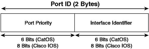
 63), while Cisco IOS uses 8 bits (allowing for a configuration range of 0
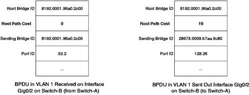


EAN: 2147483647
Pages: 135
- ERP System Acquisition: A Process Model and Results From an Austrian Survey
- Distributed Data Warehouse for Geo-spatial Services
- Data Mining for Business Process Reengineering
- Intrinsic and Contextual Data Quality: The Effect of Media and Personal Involvement
- A Hybrid Clustering Technique to Improve Patient Data Quality