Scenario 2-1: Understanding Transparent Bridging
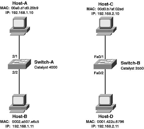
| Before you learn how to configure VLANs, it is important that you have a firm understanding of transparent bridging, because it is the underlying fundamental of Ethernet switching. Figure 2-1 described the transparent bridging algorithm that is used by switches, and Figure 2-2 demonstrated how frames are transparently bridged. In this scenario, you learn how to verify transparent bridging operation. Figure 2-6 shows the topology used for this scenario. Figure 2-6. Scenario 2-1 Topology
In Figure 2-6, two separate LANs are used to demonstrate transparent bridging on a CatOS switch (Switch-A) and on a Cisco IOS switch (Switch-B). Each switch has hosts connected, with MAC addresses and IP addresses indicated. IP is required only to provide a protocol that requires transport via the LAN; the MAC addresses are required to verify transparent bridging operation. Configuration TasksCisco Catalyst switches inherently support transparent bridging, as this is how they forward frames between Layer 2 devices. As such, no explicit configuration is required to enable transparent bridging on Cisco Catalyst switches, which means you can conceivably power on a new switch, connect devices to it, and the devices will be able to communicate at a Layer 2 level without any configuration of the switch. NOTE The exceptions to needing no explicit configuration are the Catalyst 6000/6500 switches operating in native IOS mode (Cisco IOS-based). These switches are Layer 3 switches, which means they possess Layer 2 switching and Layer 3 routing capabilities. By default, all interfaces on these switches are routed interfaces (i.e., identical to Ethernet interfaces on a traditional router) and are in a shutdown state, meaning you must explicitly enable each interface and configure each as a Layer 2 interface to enable Layer 2 switching. The native IOS Catalyst 6000/6500 is discussed in detail in Chapter 6, "Layer 3 Switching." In this scenario, you see how an unconfigured Cisco Catalyst switch performs transparent bridging by looking at the bridge table on each switch. The bridge table contains forwarding information that includes destination MAC addresses, the egress ports that frames with a particular destination MAC address should be sent out, and the age of each entry. The ability to view the bridge table on a switch is a fundamental skill that any LAN administrator or engineer should possess and provides you with the information you need to ensure transparent bridging is operating correctly. Verifying Transparent Bridging on CatOSTo view the bridge table on a CatOS switch, use the show cam dynamic command. This command displays all entries within the bridge table that have been dynamically learned by the inspection of the source MAC address of frames received (i.e., the learning process of transparent bridging). Example 2-1 demonstrates the use of this command on Switch-A, before any hosts have been connected to the switch. Example 2-55. Displaying the Bridge Table on Switch-A with No Hosts ConnectedConsole> (enable) show cam dynamic * = Static Entry. + = Permanent Entry. # = System Entry. R = Router Entry. X = Port Security Entry $ = Dot1x Security Entry VLAN Dest MAC/Route Des [CoS] Destination Ports or VCs / [Protocol Type] ---- ------------------ ----- ------------------------------------------- Total Matching CAM Entries Displayed =0 In Example 2-1, you can see that there are no dynamic entries in the bridge table, as no hosts are connected to the switch. The shaded line indicates the fields that make up the bridge table. The following describes each field:
Now, assume that Host-A is attached to the switch and attempts to send data to Host-B. Because these hosts are using IP to communicate, Host-A sends an Address Resolution Protocol (ARP) request frame, which is sent to the ffff.ffff.ffff broadcast address, and asks for the MAC address of the host associated with the IP address of Host-B (192.168.1.11). The ARP request also includes a source MAC address of 00a0.d1d0.20b9, which is learned by the switch upon reception and placed into the bridge table. Because the ARP request is received on port 2/1, the destination port for the entry will be port 2/1. Host-B is not connected to the switch so the ARP request will never be answered; however, even though no communications have actually successfully taken place between devices connected to the switch, a bridge table entry has been generated. Example 2-2 demonstrates the use of the show cam dynamic command after Host-A has been attached to port 2/1 and has attempted to communicate with Host-B. Example 2-56. Displaying the Bridge Table after Host-A Transmits to Host-B Console> (enable) show cam dynamic * = Static Entry. + = Permanent Entry. # = System Entry. R = Router Entry. X = Port Security Entry $ = Dot1x Security Entry VLAN Dest MAC/Route Des [CoS] Destination Ports or VCs / [Protocol Type] ---- ------------------ ----- ------------------------------------------- 1 00-a0-d1-d0-20-b9 2/1 [ALL] Total Matching CAM Entries Displayed =1 Notice in Example 2-2 that a single entry is now displayed. The VLAN indicated is VLAN 1 (which is the default VLAN that all ports are placed into), the destination MAC address is the MAC address of Host-A, and the destination port is port 2/1, which is indeed the port that Host-A is attached to. If frames are received in VLAN 1 by Switch-A that have a destination MAC address of 00-a0-d1-d0-20-b9, Switch-A now possesses the necessary information to forward the frame out port 2/1 to Host-A, instead of having to flood the frame out all ports (except the port the frame was received on). Now, assume that Host-B is attached to Switch-A and that Host-A once again attempts to communicate with Host-B. The ARP request is a broadcast frame, so Switch-A forwards the frame out all ports, except for port 2/1. Host-B receives the broadcast and responds to the ARP request with an ARP reply, which indicates it is the host that possesses the IP address 192.168.1.11. The ARP reply is sent as a unicast frame back to Host-A, which means the source MAC address of the frame will be 00-02-a5-07-e6-c5 (Host-B) and the destination MAC address will be 00-a0-d1-d0-20-b9. When Switch-A receives this frame, it learns that Host-B is reachable via port 2/2, and it also forwards the frame out port 2/1 to Host-A, because of the entry in the bridge table for the MAC address of Host-A. Example 2-3 demonstrates the bridge table on Switch-A after the ARP reply is sent from Host-B to Host-A. Example 2-57. Displaying the Bridge Table on Switch-A After Host-B Replies to Host-A Console> (enable) show cam dynamic * = Static Entry. + = Permanent Entry. # = System Entry. R = Router Entry. X = Port Security Entry $ = Dot1x Security Entry VLAN Dest MAC/Route Des [CoS] Destination Ports or VCs / [Protocol Type] ---- ------------------ ----- ------------------------------------------- 1 00-a0-d1-d0-20-b9 2/1 [ALL] 1 00-02-a5-07-e6-c5 2/2 [ALL] Total Matching CAM Entries Displayed =2 Notice in Example 2-3 that a new entry has been added for Host-B. Example 2-2 and Example 2-3 demonstrate how the bridge table can be populated very quickly, minimizing the flooding of traffic sent to an unknown destination MAC address. It is important to note that you can also manually add static entries to the bridge table, with the option of making those entries permanent so that they remain in the bridge table even after a shutdown or reboot. To configure static bridge table entries on CatOS, use the following command: set cam {static | permanent} mac_address mod/port vlan If you specify the static keyword, the bridge table entry remains in the bridge table until the bridge table is cleared (using clear cam command) or until the switch is shutdown/rebooted. If you specify the permanent keyword, the entry remains in the bridge table permanently, even after a switch reboot. Example 2-4 demonstrates configuring a static entry for Host-B. Example 2-58. Configuring a Static Bridge Table Entry on Switch-A Console> (enable) set cam static 00-02-a5-07-e6-c5 2/2 1 Static unicast entry added to CAM table. It is important that you specify the MAC address as indicated in Example 2-4. The command configures a destination port of 2/2 and a VLAN of 1. To view static or permanent entries, you must use the show cam static or show cam permanent commands. NOTE You typically never need to configure static CAM entries on a switch, except possibly for multicast traffic, if you are not using multicast traffic control features on your switch. By configuring static CAM entries for a destination multicast address, you can constrain multicast traffic to a specific set of destination ports, instead of having the switch flooding the multicast out all ports. Verifying Transparent Bridging on Cisco IOSTo view the bridge table on a Cisco IOS switch, use the show mac-address-table dynamic command. This command displays all entries within the bridge table that have been dynamically learned by the inspection of the source MAC address of frames received (i.e., the learning process of transparent bridging). Example 2-5 demonstrates the use of this command on Switch-B, before any hosts have been connected to the switch. Example 2-59. Displaying the Bridge Table on Switch-B Switch# show mac-address-table dynamic Mac Address Table ------------------------------------------ Vlan Mac Address Type Ports ---- ----------- ---- ----- In Example 2-5, you can see that the bridge table is fairly similar in structure to the bridge table output on CatOS. The Type field indicates whether the entry is dynamic, static, permanent, and so on. Now, assume that Host-C is attached to the switch and attempts to send data to Host-D. Following the same process as described in the previous section, Switch-B adds an entry to the bridge table for the MAC address of Host-C. Example 2-6 demonstrates the bridge table on Switch-B after Host-C has been attached to interface Fa0/1 and has attempted to communicate with Host-D. Example 2-60. Displaying the Bridge Table on Switch-B Switch# show mac-address-table dynamic Mac Address Table ------------------------------------------ Vlan Mac Address Type Ports ---- ----------- ---- ----- 1 00d0.b7af.02ed DYNAMIC Fa0/1 Total Mac Addresses for this criterion: 1 In Example 2-6, a new entry has been added to the bridge table that associates Host-C with the egress interface Fa0/1. NOTE Notice that on Cisco IOS the nomenclature for representing MAC addresses uses a xxxx.xxxx.xxxx format, as opposed to xx-xx-xx-xx-xx-xx on CatOS. There is absolutely no difference between MAC addresses represented in either format. Now assume that Host-D is attached to Switch-B and that Host-C once again attempts to communicate with Host-D. Again following the same process as discussed in the previous section, an entry is added to the bridge table for the MAC address of Host-D. Example 2-7 demonstrates the bridge table on Switch-A after Host-D communicates with Host-C. Example 2-61. Displaying the Bridge Table on Switch-B Switch# show mac-address-table dynamic Mac Address Table ------------------------------------------ Vlan Mac Address Type Ports ---- ----------- ---- ----- 1 00d0.b7af.02ed DYNAMIC Fa0/1 1 0001.422c.6796 DYNAMIC Fa0/2 Total Mac Addresses for this criterion: 1 You can manually add static entries to the bridge table on Cisco IOS, which are placed permanently in the bridge table. To configure static bridge table entries on Cisco IOS, use the following global configuration mode command: Switch(config)# mac-address-table static mac-address vlan vlan-id interface interface-id The mac-address parameter must be specified in xxxx.xxxx.xxxx format. Unlike static entries on CatOS that are only placed into the bridge table until the switch is shutdown/rebooted, static entries on Cisco IOS are the equivalent of permanent entries on CatOS in that they remain in the bridge table even after a switch shutdown/reboot. Example 2-8 demonstrates configuring a static entry for Host-C on Switch-B: Example 2-62. Configuring a Static Bridge Table Entry on Switch-BSwitch# configure terminal Switch(config)# mac-address-table static 00d0.b7af.02ed vlan 1 interface fa0/1 To view static entries, use the show mac-address-table static command. |
EAN: 2147483647
Pages: 135